
626 L4-1998 cc 2.0L SOHC Turbo FE (1986)
EGR Valve Position Sensor: Testing and Inspection
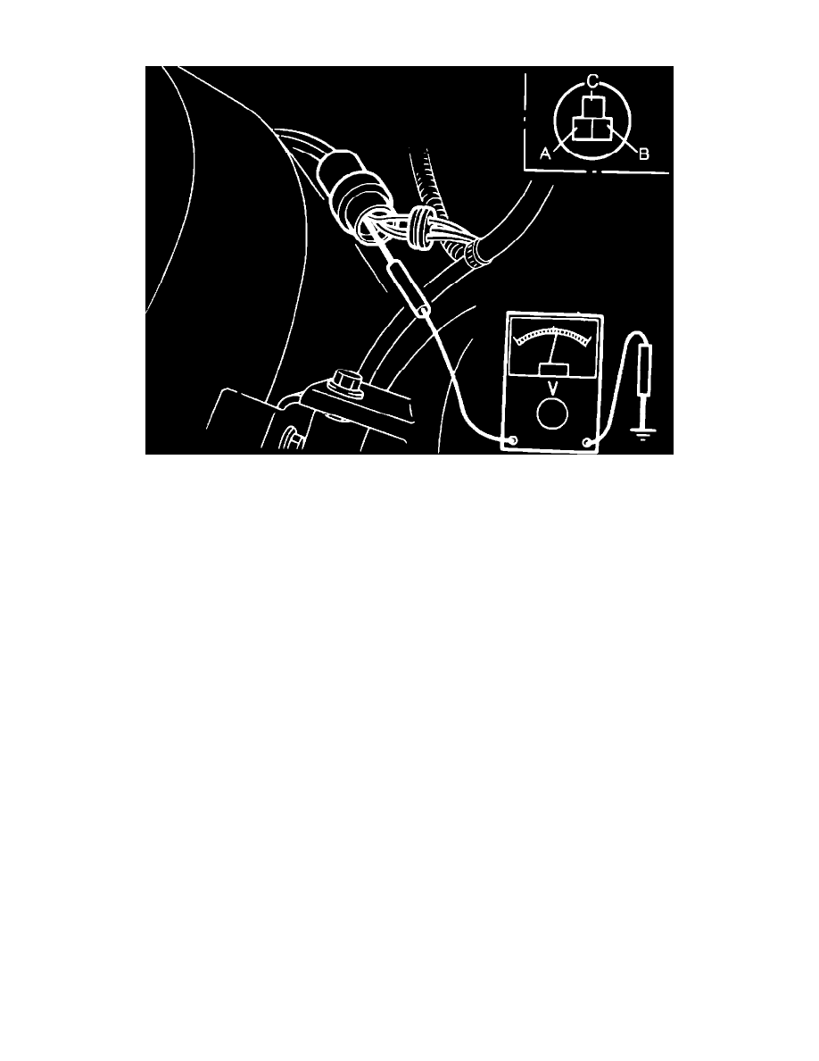
Fig. 77 EGR position sensor connector terminal identification. Turbocharged models
1.
Remove rubber boot from connector.
2.
Disconnect vacuum hose from EGR control valve and, using vacuum pump, apply vacuum to valve.
3.
Turn ignition switch to ``On.''
4.
Using voltmeter, check voltage of each terminal, Fig. 77. Voltage at terminal C should be approximately .7 volt with no vacuum applied and
approximately 4.7 volts with 5.9 inches Hg vacuum applied, voltage at terminal B should be less than 1.5 volts regardless of vacuum applied and
voltage at terminal A should be 4.5-5.5 volts regardless of vacuum applied.
5.
If reading is incorrect at terminals A and B, check wiring harness and EGI control unit.
6.
If voltage is incorrect at terminal C, check resistance of sensor, then the wiring harness and EGI control unit.
7.
Check resistance of sensor as follows:
a. Disconnect connector of sensor.
b. Remove rubber boot from connector.
c. Check resistance between terminals. Resistance should be 5k ohms between terminals A and B and .7-5k ohms between terminals A and C
and between terminals B and C.