
626 L4-2.0L DSL (1984)
(1)
Remove A/C relay #2 from connector.
(2)
Apply 12 volts to terminals 1 & 2 as shown.
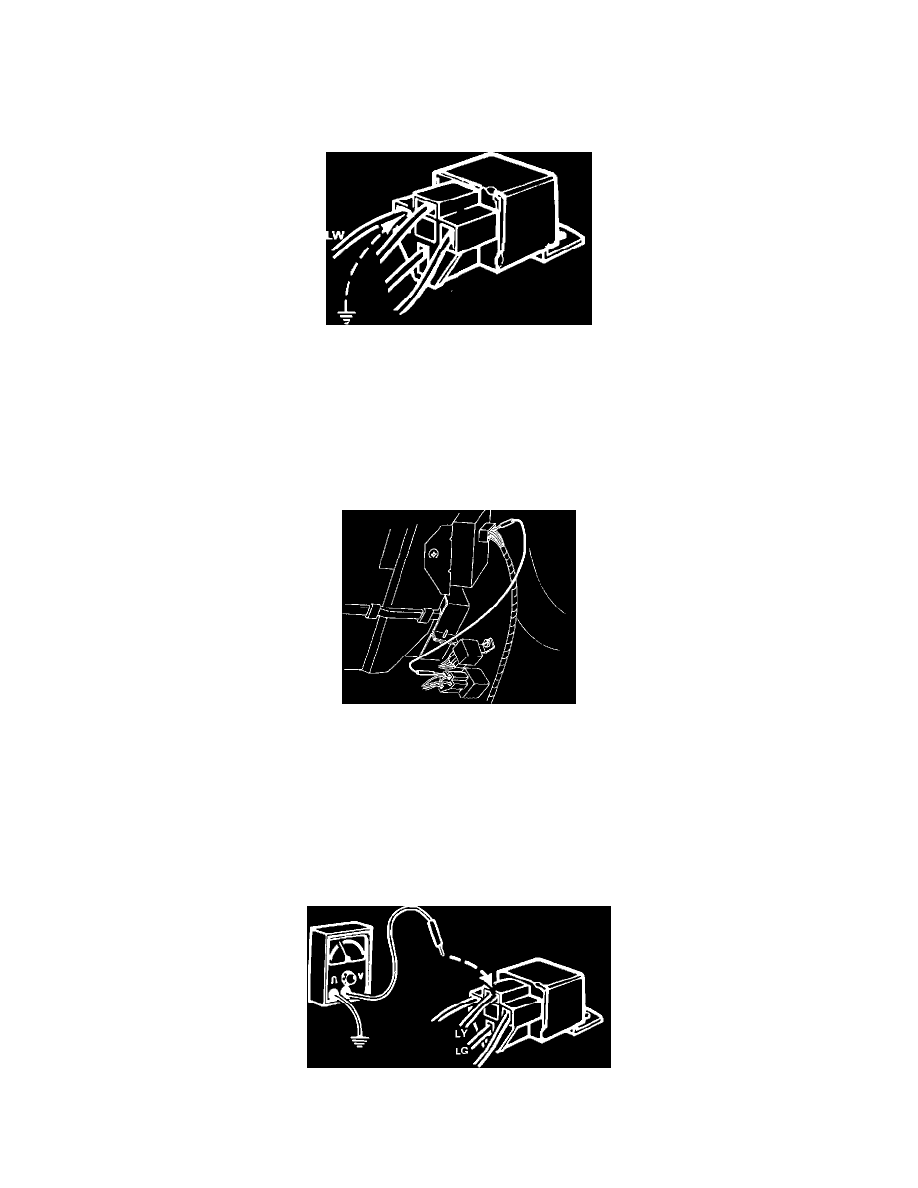
(3)
Using an OHM meter, check for continuity between terminals 3 & 4 as shown.
^
If continuity exists, reconnect the A/C relay #2 and proceed to step 19.
^
If no continuity exists, replace the relay.
BLUE-WHITE WIRE GROUND AT A/C RELAY #2 CONNECTOR
Step 19. Ground the blue-white wire at the A/C relay #2 connector.
CHECKING RESULTS
A.
If the compressor clutch engages, proceed to Step 20.
B.
If the compressor clutch does not engage, proceed to Step 21.
JUMPER WIRE BLUE-WHITE WIRE TO S.H.S. CONNECTOR
Step 20. Use a jumper wire between the blue-white wire of the A/C relay #2 connector and the blue-white wire of the S.H.S. control box connector.
CHECKING RESULTS
A.
If the compressor clutch engages, check the blue-white wire for a loss of continuity between A/C relay #2 connector and S.H.S. control box
connector.
B.
If the compressor clutch does not engage, replace the S.H.S. control box.
BLUE-YELLOW WIRE CHECK