
626 L4-2.0L DSL (1984)
Constant Velocity Joint: Service and Repair
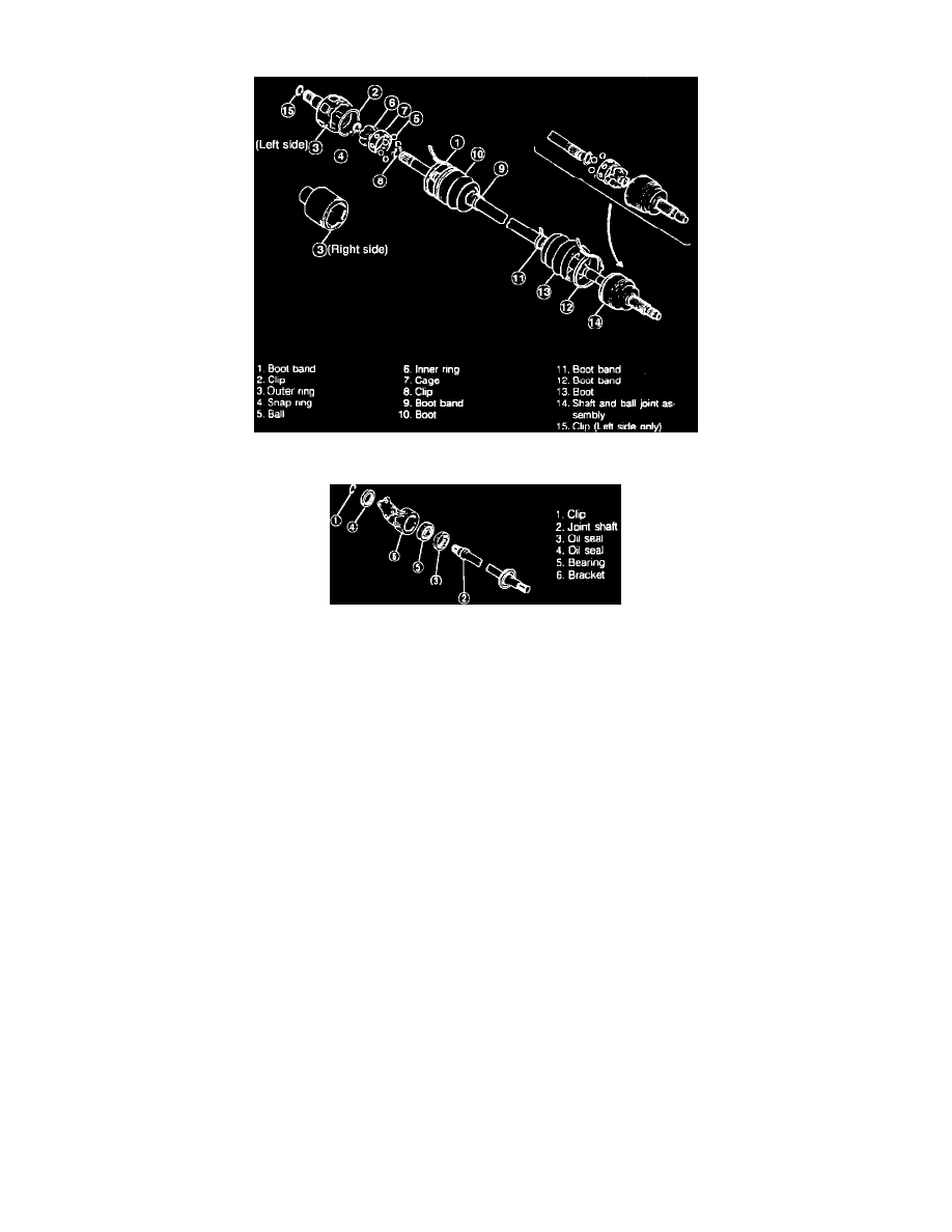
Fig. 5 Exploded view of driveshaft. 1984-87 626 w/manual transaxle
Fig. 6 Exploded view of joint shaft & bracket assembly. 1984-87 626
Disassembly, Models W/Manual Transaxle
Disassemble driveshaft in numerical order, Fig. 5, noting the following:
1.
When securing shaft in vise, use protective material on vise jaws.
2.
Ensure dust or other foreign matter does not get inside joint while work is being done.
3.
Do not disassemble ball joint at wheel side and do not wipe off grease unless necessary.
4.
To remove boot band, pry up locking clip with screwdriver, then raise end of band.
5.
Use flat tipped screwdriver to remove clip.
6.
Use suitable pliers to remove snap ring.
7.
Pull balls, inner ring and cage out from shaft as a complete assembly and insert a flat tipped screwdriver between inner ring and cage to remove
balls, then turn cage approximately 30 degrees and pull it away from inner ring. Before disassembling, scribe alignment mark.
8.
Disassemble joint shaft and bracket assembly in numerical order, Fig. 6, noting the following:
a. To remove joint shaft, support bearing and press off. Hold shaft by hand, ensuring it does not drop.
b. To remove bearing, support bracket and press off.