
626 L4-2.0L DSL (1984)
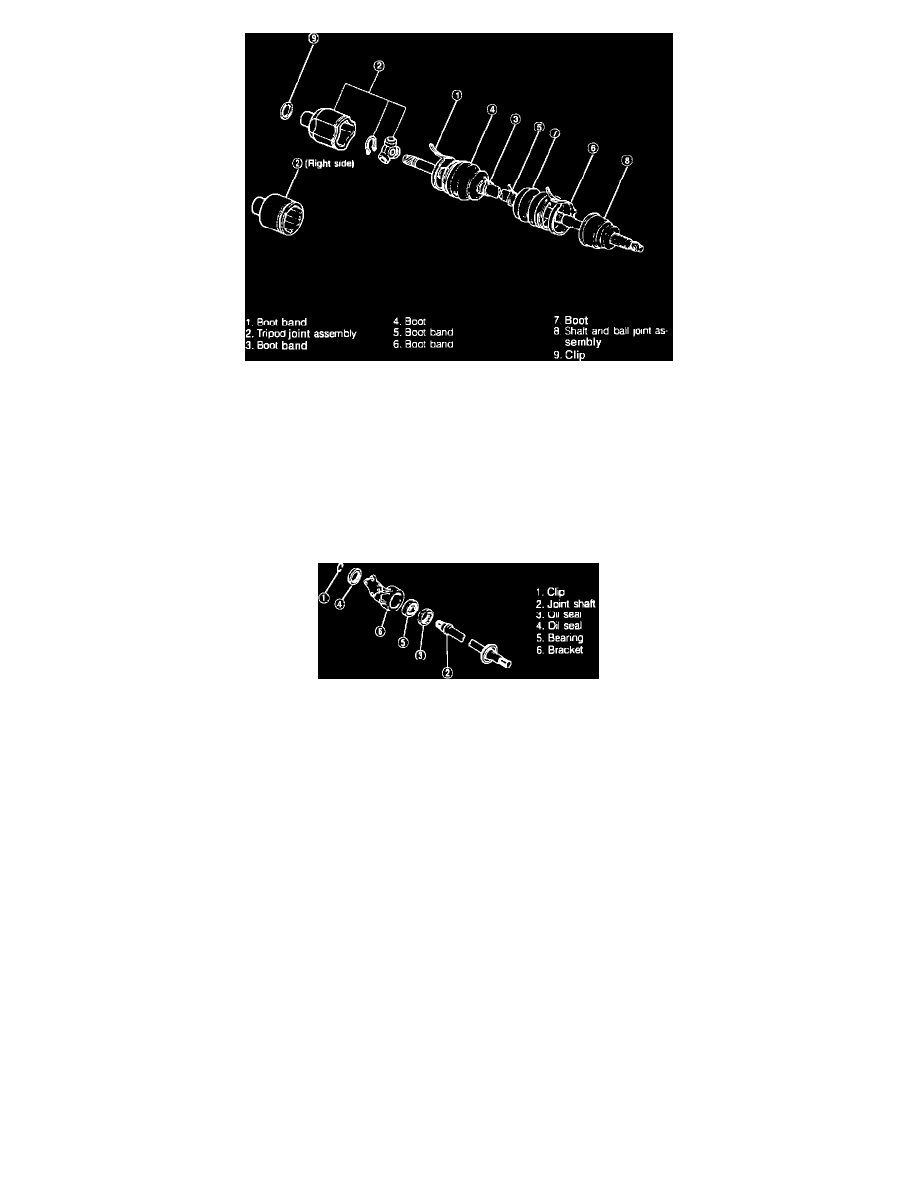
Fig. 7 Exploded view of driveshaft. 1984-87 626 w/automatic transaxle
Disassembly, Models W/Automatic Transaxle
Disassemble driveshaft in numerical order, Fig. 7, noting the following:
1.
When securing shaft in vise, use protective material on vise jaws.
2.
Ensure dust or other foreign matter does not get inside joint while work is being done.
3.
Do not disassemble ball joint at wheel side and do not wipe off grease unless necessary.
4.
To remove boot band, pry up locking clip with screwdriver, then raise end of band.
5.
Remove snap ring with suitable tool, then remove tripod joint bearing.
Fig. 6 Exploded view of joint shaft & bracket assembly. 1984-87 626
6.
Disassemble joint shaft and bracket assembly in numerical order, Fig. 6, noting the following:
a. To remove joint shaft, support bearing and press off. Hold shaft by hand, ensuring it does not drop.
b. To remove bearing, support bracket and press off.
Inspection
1.
Check for twisted, bent or damaged shaft, replacing as necessary.
2.
Check for wear or scoring of splines, replacing as necessary.
3.
Check for wear, excessive looseness, seizure, rust or damage to ball joint, replacing as necessary. Turn joint completely to check it.
4.
Check for cracks, damage or deterioration of boots, replacing as necessary.
5.
Check for excessive play or heat damage of joint shaft bearing, replacing as necessary.
Assembly, Models W/Manual Transaxle
1.
After wrapping tape around spline of shaft and ball joint assembly, attach boot at wheel side, noting the following:
a. The wheel side and differential side boots are different, do not intermix.
b. Fill inside of ball joint with grease included in kit.
c. Correctly fit boot onto shaft and outer race boot groove.
2.
Secure wheel side boot with new boot band as follows:
a. Fold band back, pulling on end with pliers.
b. Lock end of band by bending locking clip.
3.
After fitting new boot band (the part with smaller diameter) to shaft, attach differential side boot.
4.
Attach clip to clip groove in shaft.
5.
Assemble cage, inner race and balls as follows: