
626 L4-2.0L DSL (1984)
Wheel Hub: Service and Repair
Removal
1.
Raise and support vehicle and remove front wheel.
2.
Loosen tie rod end nut, then, using tool 490118850C or equivalent, separate tie rod end from knuckle. If removal is difficult, tap ball joint
coupling with hammer.
3.
Detach stabilizer bar control link from lower arm.
4.
Uncrimp and remove driveshaft locknut. When removing nut, depress brake pedal to secure hub.
5.
Remove flex hose clip and detach flexible hose from shock absorber.
6.
Remove caliper assembly, leaving hose attached, and suspend out of way.
7.
Remove ball joint to knuckle attaching nut and bolt, then push lower arm downward to disconnect ball joint from knuckle.
8.
Remove shock absorber to knuckle attaching bolts.
9.
Disconnect front hub and knuckle from driveshaft. If driveshaft cannot be separated from front hub, use tool 490839425C or equivalent.
Disassembly
Do not disassemble dust cover and disc plate unless necessary.
1.
Mount tool 49G030725 or equivalent onto knuckle and tool 49G030727 or equivalent onto edge of wheel hub, then secure knuckle in suitable vise
and turn bolt to disconnect wheel hub and disc plate assembly from knuckle. Use nut and bolt from vehicle to install and loosely tighten puller
to knuckle ball joint.
2.
Remove snap ring.
3.
Mount tool 49G030728 or equivalent onto edge of wheel bearing inner race, secure knuckle in suitable vise and turn bolt to remove wheel bearing
from knuckle.
4.
Scribe alignment marks on disc plate and wheel hub, then remove bolts and disassemble wheel hub and disc plate. Use copper plates when
securing disc plate in vise.
5.
Remove wheel studs from wheel hub, then the dust cover from knuckle.
Inspection
1.
Check for cracked or damaged knuckle, excessive rust at bearing coupling, rough rotation of or damaged bearing or damaged oil sea. Replace as
necessary. Bearing is packed with grease, do not clean.
2.
Check dust cover for deformation or poor fit to knuckle, replacing as necessary.
3.
Check for cracked or damaged hub, heat damage or rust at coupling part of bearing or worn contact surface of oil seal, replacing as necessary.
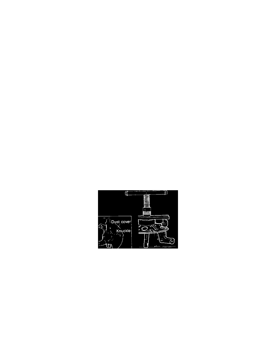
Fig. 10 Installing dust cover in knuckle. 1984-87 626
Assembly
1.
Place piece of pipe with I.D. of 3.3-3.4 inches (85-87 mm) as shown, Fig. 10, and press fit dust cover into knuckle with suitable press. Dust cover
should be in position shown, Fig. 10, with relation to knuckle.
2.
Using suitable tool, press new wheel studs into hub. Do not reuse wheel studs, install new ones.
3.
Align mating marks on disc plate and wheel hub and torque mounting bolts to 36-43 ft.lbs.
4.
Place a piece of pipe with I.D. of 2.54-2.64 inches (65-67 mm) against wheel bearing outer race and use press to press bearing into knuckle. Press
in until edge of wheel bearing contacts knuckle. The center of the part that supports the knuckle must be aligned with the center of the press
spindle. Place knuckle so that it is straight on support plate. Before insertion, check to be sure that wheel bearing oil seal has not moved
upward, pressing back into position as necessary.
5.
Install snap ring.