
626 L4-2184cc 2.2L SOHC F2 (1989)
Hydraulic Control Assembly - Antilock Brakes: Service and Repair
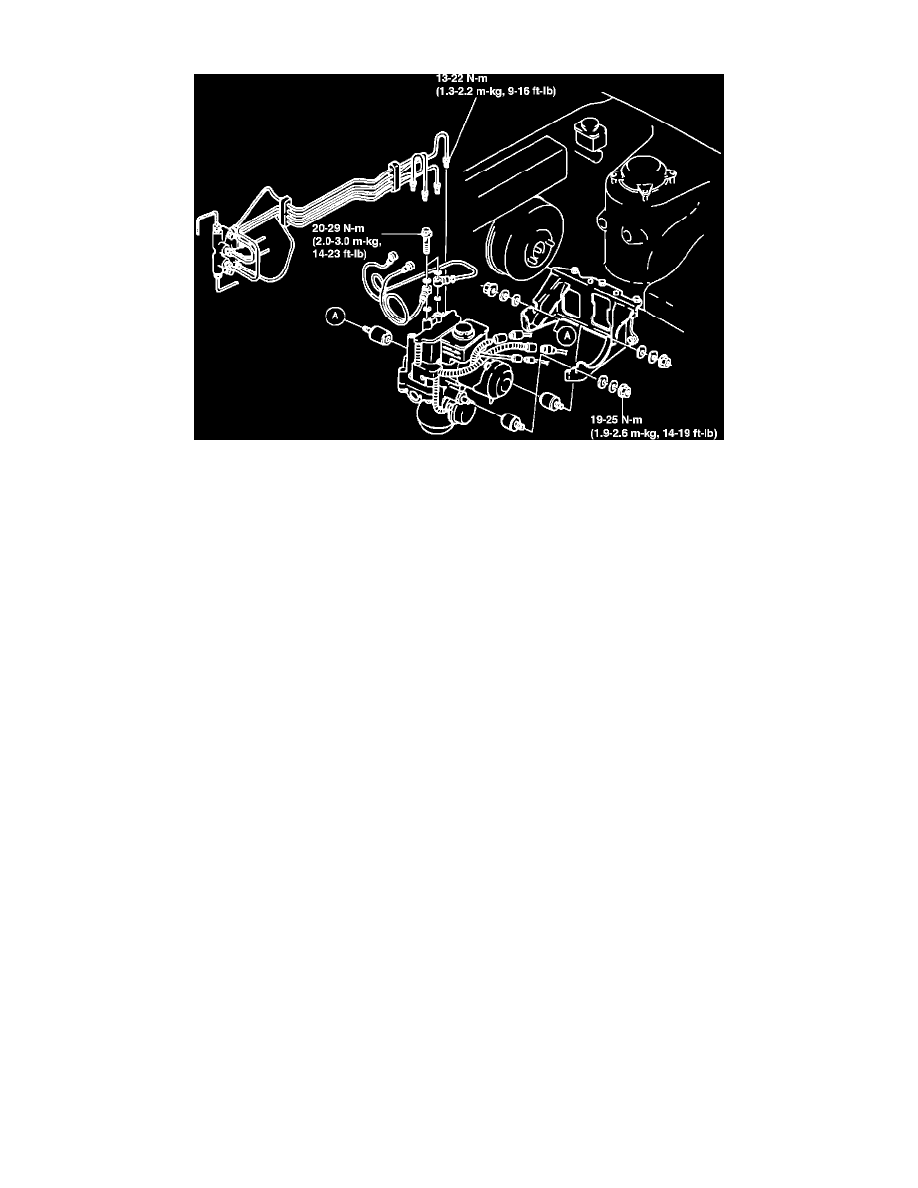
Fig. 72 Hydraulic Unit Replacement
The accumulator contains high pressure gas. Do not attempt to disassemble or subject it to hard shocks or high heat.
When the hydraulic unit is scrapped, the high pressure gas must be released. Turn the screw on the bottom of the accumulator one full turn only,
allowing gas to escape gradually.
1.
Disconnect battery ground cable.
2.
Remove igniter and fuel filter to bracket mounting bolts, then move filter and igniter toward engine.
3.
Remove air cleaner assembly, then the brake fluid level sensor connector.
4.
Remove brake pipe from master cylinder, then the master cylinder.
5.
On models with MTX, remove brake pipe holder using the SST.
6.
Remove coupler, then the brake pipes, Fig. 72.
7.
Remove mounting bushing, then the hydraulic unit.
8.
Reverse procedure to install, noting the following:
a. Torque mounting bushing nuts to 14-19 ft. lbs.
b. Torque brake pipes to 9-16 ft. lbs.
c. Torque banjo bolt (top of hydraulic unit) to 14-23 ft. lbs.
d. Fill reservoir with specified brake fluid, remove bleeder cap, then connect one end of transparent vinyl tube to bleeder screw, with the other
end in a receptacle partially filled with brake fluid.
e. Have assistant pump brake pedal, then hold in the depressed position. loosen bleeder screw, relieving pressure, then tighten screw.
f.
Repeat step E, until no more air is released. Ensure reservoir remains at least half full.
g. Torque bleeder screws to 52-78 ft. lbs., then ensure no fluid is leaking, then fill master cylinder with specified brake fluid.