
626 L4-2184cc 2.2L SOHC F2 (1989)
Idle/Bypass Air Control Valve: Description and Operation
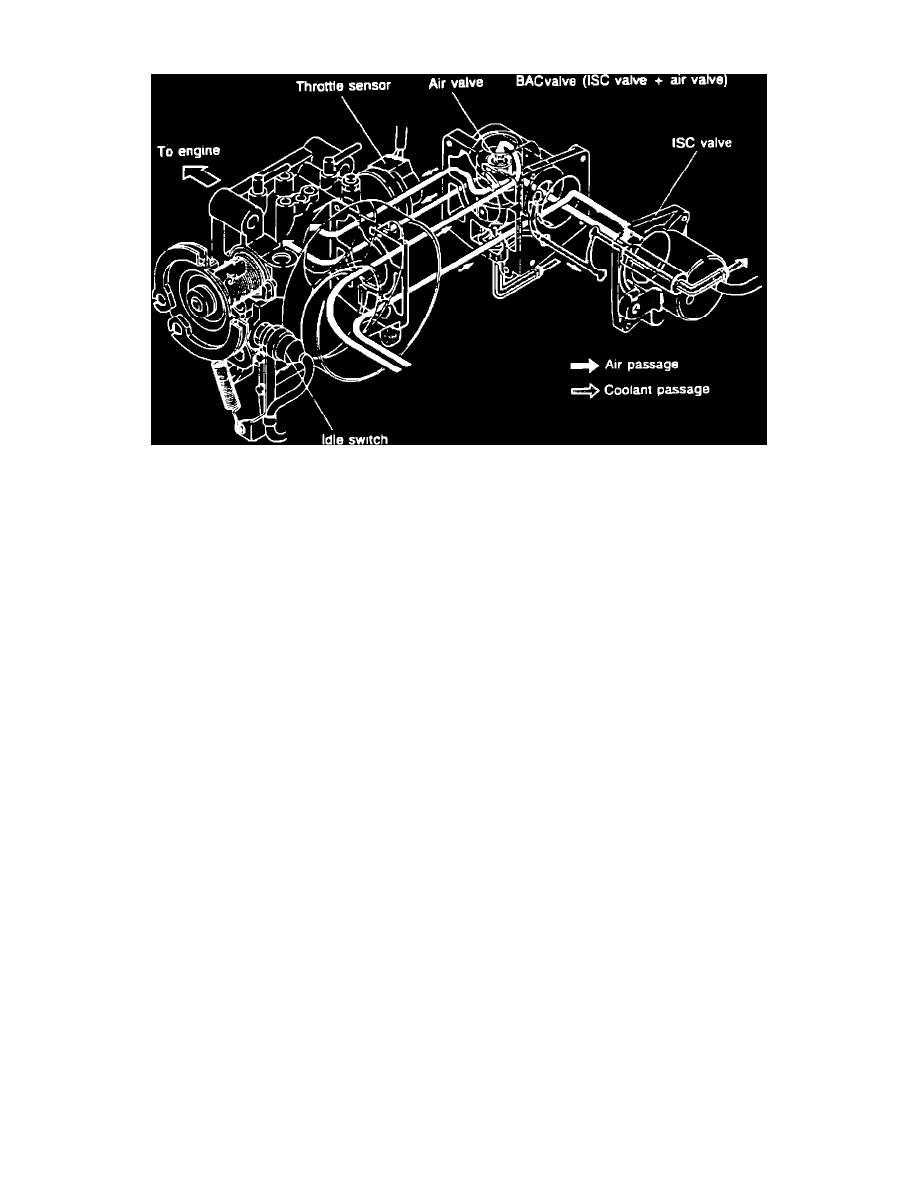
Fig. 119 Idle speed control system.
To improve idle smoothness, the idle speed control (ISC) system controls the intake air amount by regulating the bypass air amount that passes
through the throttle body. The computerized engine control related components of the idle speed control system are the bypass air control valve (BAC),
airflow meter, throttle sensor, and the idle switch.
The BAC valve consists of the air valve, which functions only during cold engine conditions (below 50° C [122°F]), and the idle speed control (ISC)
valve which works throughout the entire engine speed range.
During the warm up phase the engine receives more fuel due to the influence of an auxiliary air device (BAC valve). This is to overcome the frictional
resistance in the cold engine and to guarantee a stable idle speed.
There are increased frictional resistances present in a cold engine which must be overcome at idle speed. The engine is therefore allowed to take in
more air through the air valve by bypassing the throttle valve. Since this additional air is measured by the airflow meter and is taken into account when
the fuel is metered, the engine receives more air/fuel mixture. With a cold engine a stable idle speed can therefore be achieved.
The ISC valve is used to regulate the idle speed and keep it within a set range. The valve accomplishes this by regulating the amount of air that is
allowed to bypass the throttle plates. As the idle speed varies out of the specified range, the idle speed control valve increases the passage size, if the
idle speed is too low, or decreases the passage size, if the idle speed is too high. Since this adjustment of airflow is measured by the airflow meter and is
taken into account when the fuel is metered, the proper air/fuel mixture is maintained throughout any idle speed adjustments.
The throttle sensor is a potentiometer splined to the throttle shaft. The potentiometer rotates with the shaft as the throttle plates open and close. The
varying resistance of the potentiometer alters the reference voltage emitted from the engine control unit (ECU) and creates a signal for use as input by the
ECU.
The idle switch detects when the throttle plates are closed and sends a signal to the ECU. The idle switch is installed on the throttle body.