
626 L4-2184cc 2.2L SOHC F2 (1989)
TEST PROCEDURE
a)
Connect the engine signal monitor (49 9200 162) and the adaptor harness (49 9200 163).
b)
Set the selector switch and monitor switch to "1F."
c)
Check the voltage at idle with the blower switch ON.
With the A/C switch ON, voltage should be below 2.5 V. With the A/C switch OFF, voltage should be 12 V.
d)
If voltage readings are OK, the problem is in another component.
VIN OF PRODUCTION CHANGE
JM1GD****L1800000 (1990 Model) 1YVGD****L5100000 (1990 Model)
REPAIR PROCEDURE
If the "1F" voltage was incorrect, the E.C.U. has an internal failure. Replace the E.C.U. and the A/C relay (AC2-09).
Since the E.C.U. has not been modified, the A/C relay (AC2-09) should be replaced with a new, resistance-type relay. Used in the 1990 626/MX-6
models, the resistance-type relay prevents the surge current from flowing into the control unit.
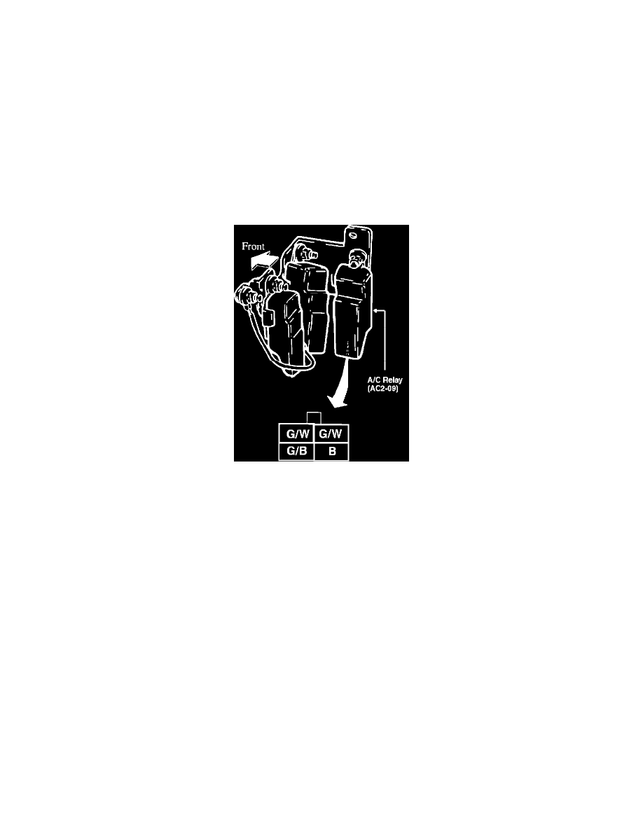
The A/C relay (AC2-09) is located below the right headlamp. There are three relays in one place. Locate the A/C relay by referring to the wire colors
illustrated.
PARTS INFORMATION
PART NUMBER DESCRIPTION
NEW
OLD
H310 67 740
FB11 67 740
A/C Relay
WARRANTY INFORMATION
Warranty Type Code:
A
Customer Comment Code:
60
Damage Code:
9W
Part No. of Main Cause:
Use E.G.I. Control Unit Part No. (see attached charts)
Quantity:
1 pc.
Operation No:
E.G.I Control Unit R&R - F0812X-R-X (0.4 Hr.) A/C Relay R&R - U0601X-R-X (0.3 Hr.)