
626 L4-2184cc 2.2L SOHC Turbo F2 (1988)
EGR Valve Position Sensor: Testing and Inspection
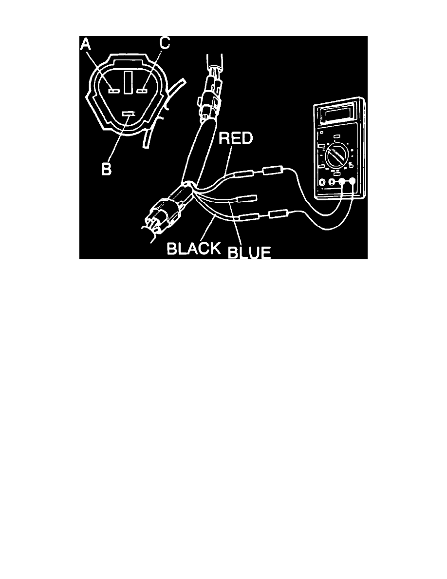
Fig. 23 EGR position sensor connector terminal identification. Turbo
OUTPUT VOLTAGE
1.
Disconnect EGR position sensor electrical connector.
2.
Connect tool 49G018901 or equivalent between EGR position sensor and wiring harness.
3.
Disconnect vacuum hose from EGR control valve and connect vacuum pump.
4.
Turn ignition switch to On position.
5.
Check voltage of each terminal, Fig. 23. With no vacuum, there should be .25---.95 volt at terminal C. With vacuum of 4.7 inches Hg, there should
be approximately 4 volts at terminal C. There should be less than 1.5 volts at terminal B and 4.5---5.5 volts at terminal A regardless of vacuum.
6.
If voltage is not satisfactory at terminals A and B, check wiring harness and engine control unit terminals 2A and 2C.
7.
If voltage is not satisfactory at terminal C, check sensor resistance, then the wiring harness and the engine control unit 2F terminal.
8.
Disconnect tool and reconnect EGR position sensor electrical connector.
RESISTANCE
1.
Disconnect EGR position sensor electrical connector.
2.
Check resistance between terminals, Fig. 23. There should be 5k ohms between terminals A and B and .7---5k ohms between terminals A and C
and between terminals B and C.