
626 V6-2496cc 2.5L DOHC (1995)
Throttle Position Sensor: Testing and Inspection
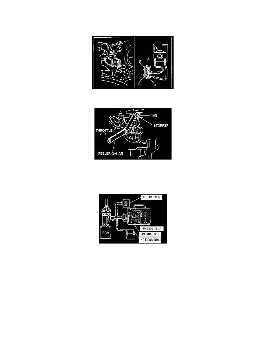
Closed Throttle Position Switch
1. Verify that the throttle valve is closed throttle position.
2. Disconnect the throttle position sensor connector.
3. Check for continuity between throttle position sensor connector terminals C and D by using an ohmmeter.
4. If no continuity, adjust the throttle position sensor.
5. Insert a 0.50 mm (0.020 in) feeler gauge between the throttle adjusting screw (TAS) and the throttle lever. Verify that there is no continuity.
6. If there is continuity, adjust the throttle position sensor.
Throttle Position Sensor
1. Remove the ECM.
2. Connect the SSTs to the ECM.
3. Verify that the throttle valve is closed throttle position.
4. Turn the ignition switch to ON.
5. Measure the ECM terminal 2F voltage by using a voltmeter.
Specification
Closed throttle position: 0.1-1.1 V Wide open throttle: 2.8-4.5 V (Verify that the voltage increase is directly proportioned to the throttle
valve opening angle.)
6. If not as specified, adjust the throttle position sensor.