
626 ES V6-2.5L DOHC (1997)
Action Chart
Step 1
1. Remove the column cover.
2. Turn the ignition switch to ON.
3. Turn the turn switch on (left or right).
4. Measure the voltage at terminal G (G/Y) or H (B/R) of the combination switch connector.
Voltmeter Connection
Action Chart
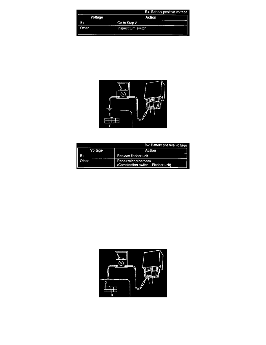
Step 2
1. Turn the turn switch on (left or right).
2. Measure the voltage at terminal F (G/Y) or E (B/R) of the flasher unit connector.
Pinpoint Test 5
Flowchart No.5 Symptom Left or right turn signal function and hazard light function do not operate
Possible Cause
^
Damaged flasher unit
^
Burnt light bulbs
^
Open or short circuit in wiring harness Poor connection of connector
Voltmeter Connection