
626 ES V6-2.5L DOHC (1997)
SSTs Engine Signal Monitor
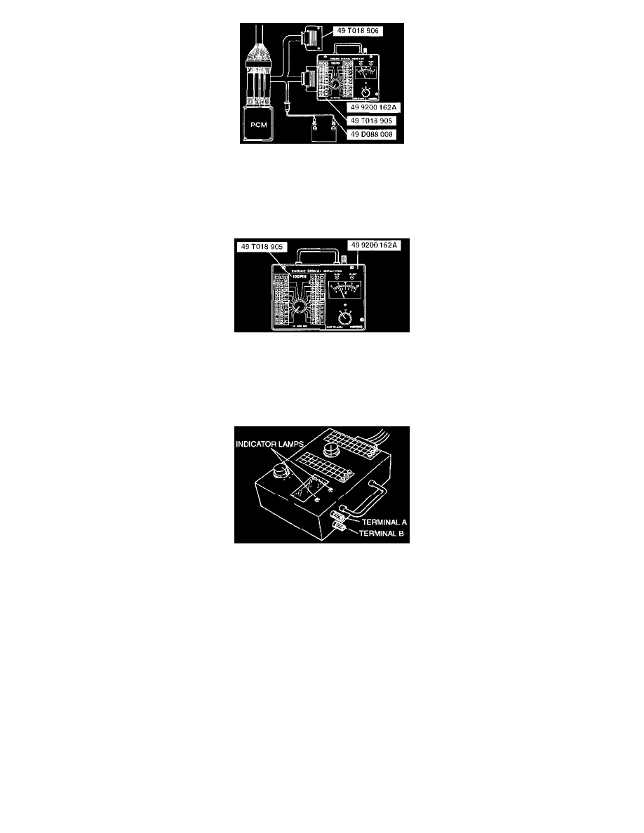
4. Connect the Special Service Tool (SST) (Adapter harness) to the PCM connector.
5. Connect the SSTs (Monitor, Engine Signal and Harness adapter, power) to the SST (Adapter harness). Use connector A of the adapter harness for
PCM terminals 1A through 1AJ and 2A through 2T, and 3A through 3R. Use connector B for PCM terminals 3S through 3AB and 4A through
4AN.
SSTs Engine Signal Monitor Details
6. Place the SST (Sheet) on the SST (Monitor, Engine Signal).
7. Measure the voltage at each PCM terminal by switching the selector switch and the monitor switch.
8. If any incorrect voltage is detected, check related systems, wiring harnesses and connectors referring to the possible malfunction in the terminal
voltage list.
SSTs Engine Signal Monitor Details
CAUTION:
-
Disconnecting the connectors of the PCM and the SST (Adapter harness) while the battery is connected can damage the PCM and the SST
(Monitor, Engine Signal). Disconnect the negative battery cable and the SST (Harness adapter, power) before disconnecting the connectors.
-
Applying voltage to terminals A and B of the SST (Monitor, Engine Signal) can damage the SST (Monitor, Engine Signal).
NOTE:
-
The indicator lights of the SST (Monitor, Engine Signal), provided for confirmation of the voltmeter range, is also used for detection of the
pulse such as the fuel injector control signal, which is difficult to detect by using the voltmeter.
-
Terminals A and B of the SST (Monitor, Engine Signal) are for connection of an external instrument. By connecting an external instrument
such as a circuit tester or an oscilloscope, various inspections in addition to the measurement of the PCM terminal voltages are made possible.