
626 LX L4-2.0L DOHC (1999)
Body Control Module: Testing and Inspection
CPU INSPECTION
1. Remove the driver's side front shaft plate.
2. Remove the driver's side front side trim.
3. Remove the nut fixed in the joint box.
4. Follow the appropriate procedure, referring to the terminal voltage list.
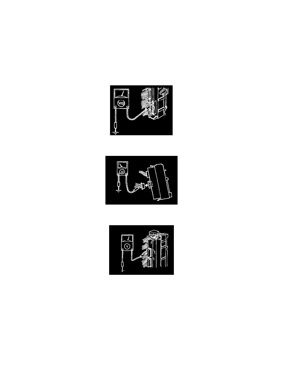
All terminals of the connector A
NOTE:
-
The voltage cannot be measured nor can a continuity to ground check be performed at the terminals of connector A with the connectors connected
to the joint box.
-
Remove the CPU from the joint box, then measure the voltage or check for continuity to ground at the CPU terminals from the joint box side with
the joint box connectors connected.
Terminals 4B and 4D of connector D
-
Disconnect the CPU connector before checking for continuity at terminals 4B and 4D as shown in the figure.
Terminals except 4B and 4D of connector D
-
Measure the voltage at the CPU connector while it is connected with the CPU as shown in the figure.
5. If not as specified, inspect' the parts listed under Inspection area" and the related wiring harnesses.
6. If the parts and wiring harnesses are okay but system still does not work properly, replace the CPU.