
626 LX L4-2.0L DOHC (1999)
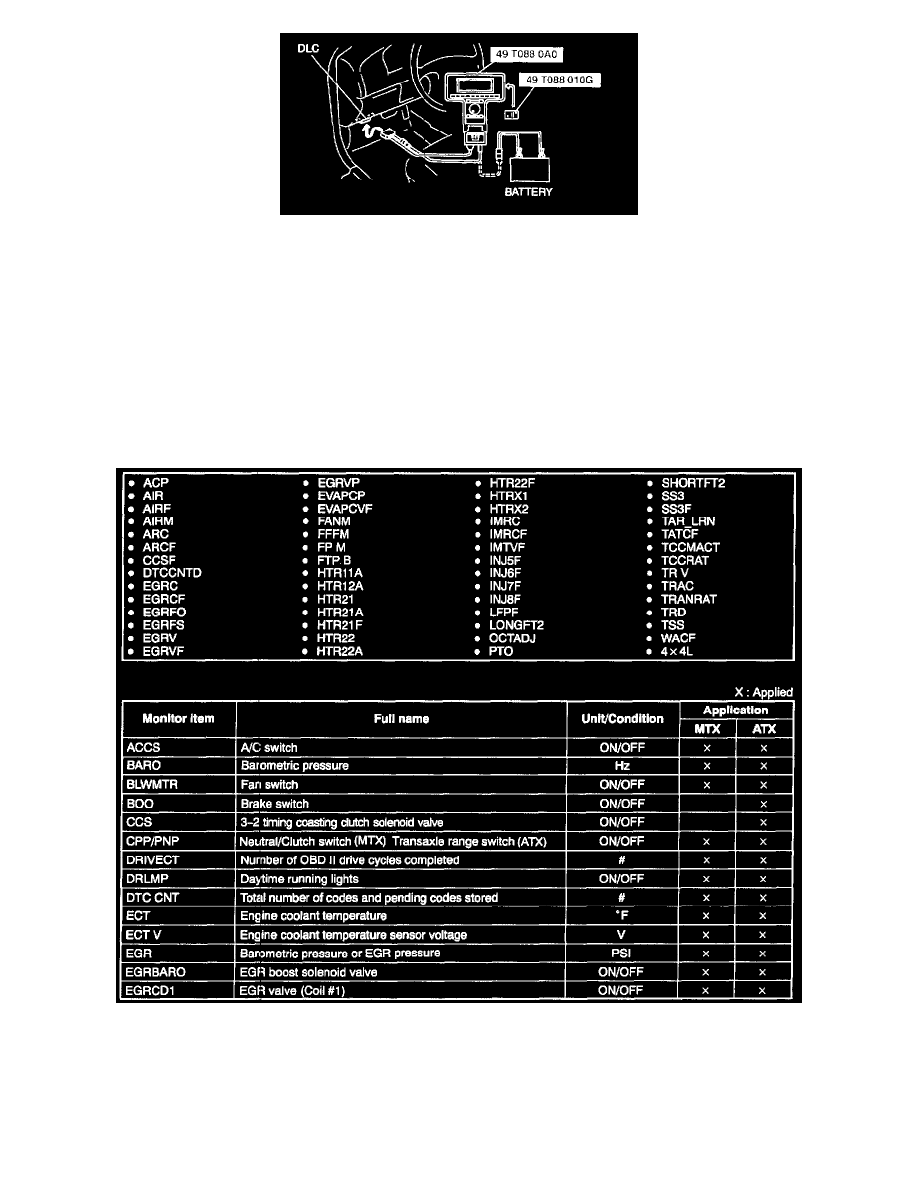
1. In the passenger compartment, connect the SSTs (NGS tester) to the data link connector.
2. Select the "PID/DATA MONITOR AND RECORD" and press TRIGGER.
NOTE:
-
The "PID/DATA MONITOR AND RECORD" function is to monitor the calculation value of input/output signals in the PCM. Deviation in
the value does not always indicate malfunction in the related input/output devices.
-
For inspection of the input/output signals other than in the link monitor table, check voltage at the applicable PCM terminal by using the SST
(104 Pin Breakout Box).
3. Press CLEAR to clear previously selected items. (A list of item descriptions appears on the screen).
4. Select items necessary and press START.
5. Carry out inspection referring to PID/DATA MONITOR table.
-
If normal output signal cannot be detected when all input signals are normal, replace the PCM