
626 LX L4-2.0L DOHC (1999)
Throttle Position Sensor: Testing and Inspection
Inspection of Output Voltage
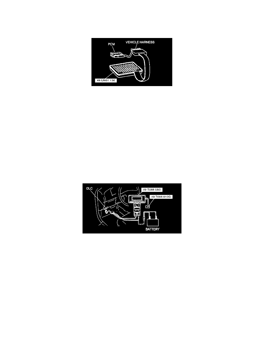
USING THE SST (104 PIN BREAKOUT BOX)
1. Remove the PCM.
2. Connect the SST (104 Pin Breakout Box) to the PCM as shown.
3. Tighten the connector attaching screws.
Tightening torque:
7.9 - 10.7 Nm {80 - 100 kg.cm, 69.5 - 95.4 in.lb.}
4. Verify that the throttle valve is at the closed throttle position.
5. Turn the ignition switch to ON.
6. Measure the PCM terminal 89 voltage by using a voltmeter.
-
If not as specified, adjust the throttle position sensor.
Specification
Closed throttle position: 0.3 - 0.7 V
Wide open throttle: 3.4 - 5.3 V
NOTE: Verify that the voltage increase is directly proportioned to the throttle valve opening angle.
USING THE SSTs (NGS TESTER)
1. Connect the SSTs (NGS tester) to the data link connector.
2. Verify that the throttle valve is at the closed throttle position.
3. Turn the ignition switch to ON.
4. Select the "PID/DATA MONITOR AND RECORD" function on the NGS tester display and press TRIGGER.
5. Select "TP V" on the NGS tester display and press START. NGS tester measures and shows the voltage.
-
If not as specified, adjust the throttle position sensor.
Specification
Closed throttle position: 0.3 - 0.7 V
Wide open throttle: 3.4 - 5.3 V
NOTE: Verify that the voltage increase is directly proportioned to the throttle valve opening angle.