
626 LX L4-2.0L DOHC (1999)
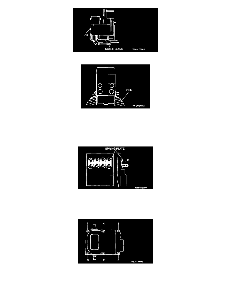
3. Carefully pull the wiring of the pump motor out of the cable guides.
4. Secure the HU as shown.
5. Remove the bolts.
6. Protect the HU from damage to the valve body and keep the sealing surface free from foreign materials.
ABS Control Module Installation Note
1. Verify that the sealing surface of the HU is clean. If there are scratches, grooves or dirt, do not mechanically rework. Carefully remove any dirt or
seal residue with plastic tools only. The use of chemical solvents is not permitted.
2. Install the spring plate properly. When re-installing, insert the spring plate over the valve bodies in the correct position to preload the spring and to
center the solenoid coils.
3. Carefully fit the coils of the ABS CM over the valve bodies.
4. Locate the ABS CM by placing the new bolts evenly against the housing and tightening them slightly by hands. To aid alignment, the housing may
be pressed onto the contact surface by hand while tightening the bolts.
5. Tighten the bolts to the specified torque in the order shown.
Tightening torque: 2.4-2.8 Nm (24-28 kgf-cm, 21-24 inch lbs.)
6. Visually inspect for all bolts mode contact. The ABS CM must be flush against the housing with no gap in the area of the bolts.