
626 LX L4-2.0L DOHC (1999)
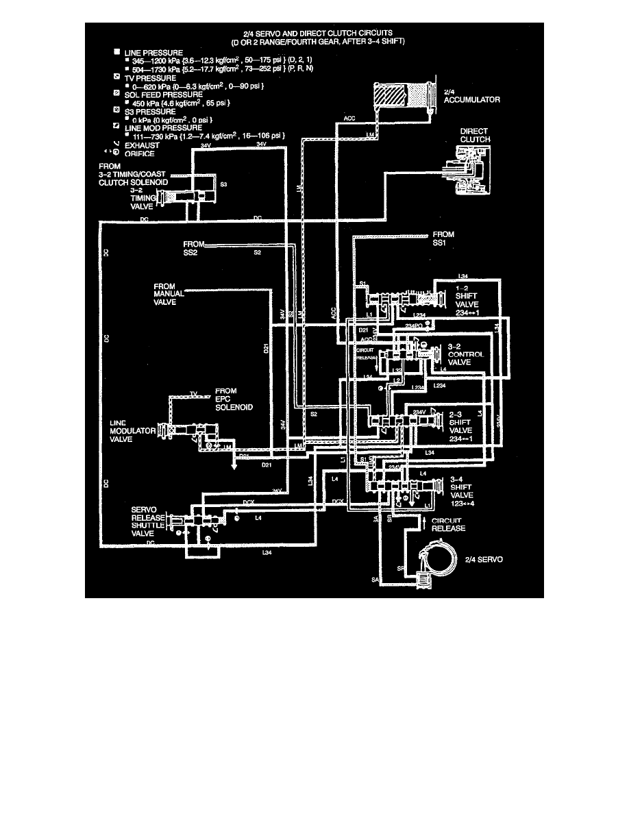
3-4 SHIFT OPERATION
The PCM controls a 3-4 shift by turning Shift solenoid 1 (SS1)ON while Shift solenoid 2 (SS2) remains OFF. This results in fluid pressure in the S1
circuit moving the 3-4 shift valve to the right side without moving the 1-2 shift valve because of the opposing pressure in the L34 circuit. In fourth
gear, the 2/4 band and the direct clutch are applied.
To apply the 2/4 band, fluid under pressure in the D21 circuit moves through the 1-2 shift valve, 2-3 shift valve and 3-4 shift valve and several
circuits. Fluid in the SA circuit from the 3-4 shift valve applies the 2/4 band. Fluid also moves through the3-2 control valve and into the ACC circuit
for the 2/4 accumulator to modulate pressure during band apply.
The direct clutch continues to receive fluid under pressure from the D21 circuit through the 2-3 shift valve. The 3-2 timing valve and 2-3 shift valve
block the exhaust path for the DC circuit through the 34V circuit.