
626 LX V6-2.5L DOHC (1997)
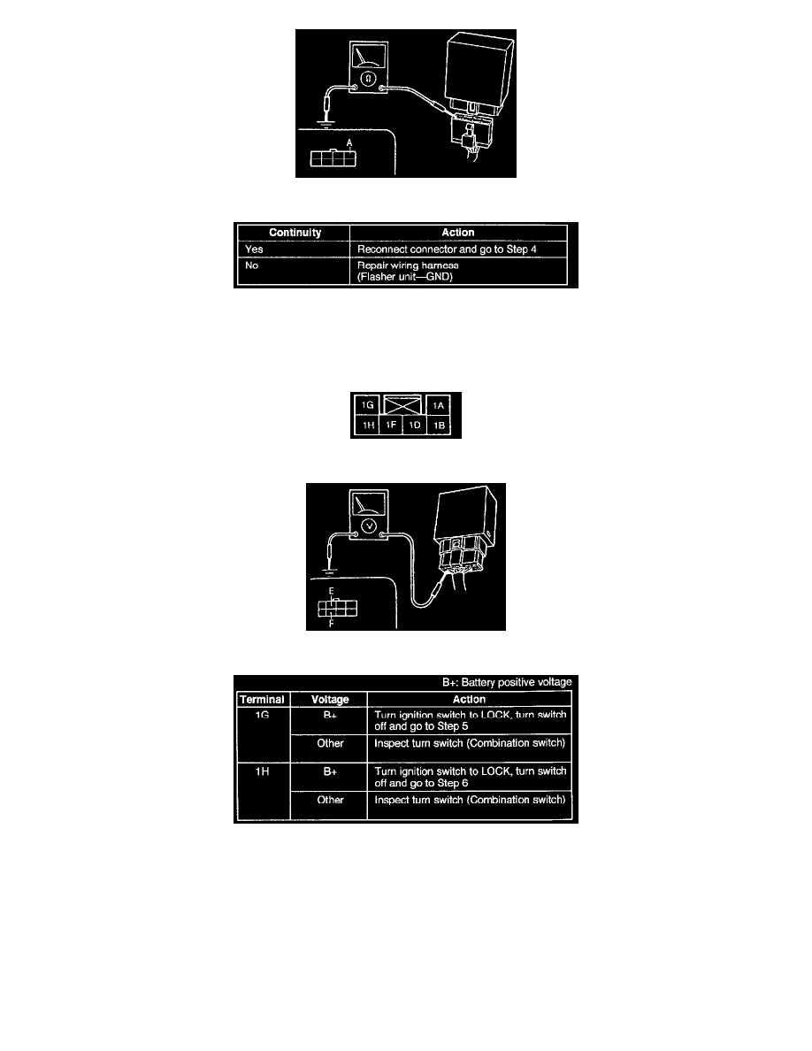
Ohmmeter Connection
Action Chart
Step 3
1. Disconnect the flasher unit connector.
2. Check for continuity between terminal A (B) of the flasher unit connector and ground.
Terminal Identification
Ohmmeter Connection
Action Chart
Step 4
1. Remove the column cover.
2. Turn the ignition switch to ON.
3. Turn the turn switch on (left or right).
4. Measure the voltage at terminal 1G (G/N) or 1H (B/R) of the combination switch connector.