
626 LX V6-2.5L DOHC (1997)
3.
Verify correct connector placement at the PRC and EGR boost sensor solenoid.
^
If the connectors are not in the proper position, correct their placement and proceed to step 6.
^
If the connectors are in the proper position, proceed to step 4.
NOTE:
^
The PRC connector (top) is BROWN and the EGR boost sensor solenoid connector (bottom) is BLACK.
^
The 1996 wiring Diagram incorrectly shows the location of these connectors for the KL engine.
4.
Inspect the EGR boost sensor.
^
Warm engine to normal operating temperature.
^
Measure the voltage between the signal wires (B/L & LG) from the rear side of the connector.
^
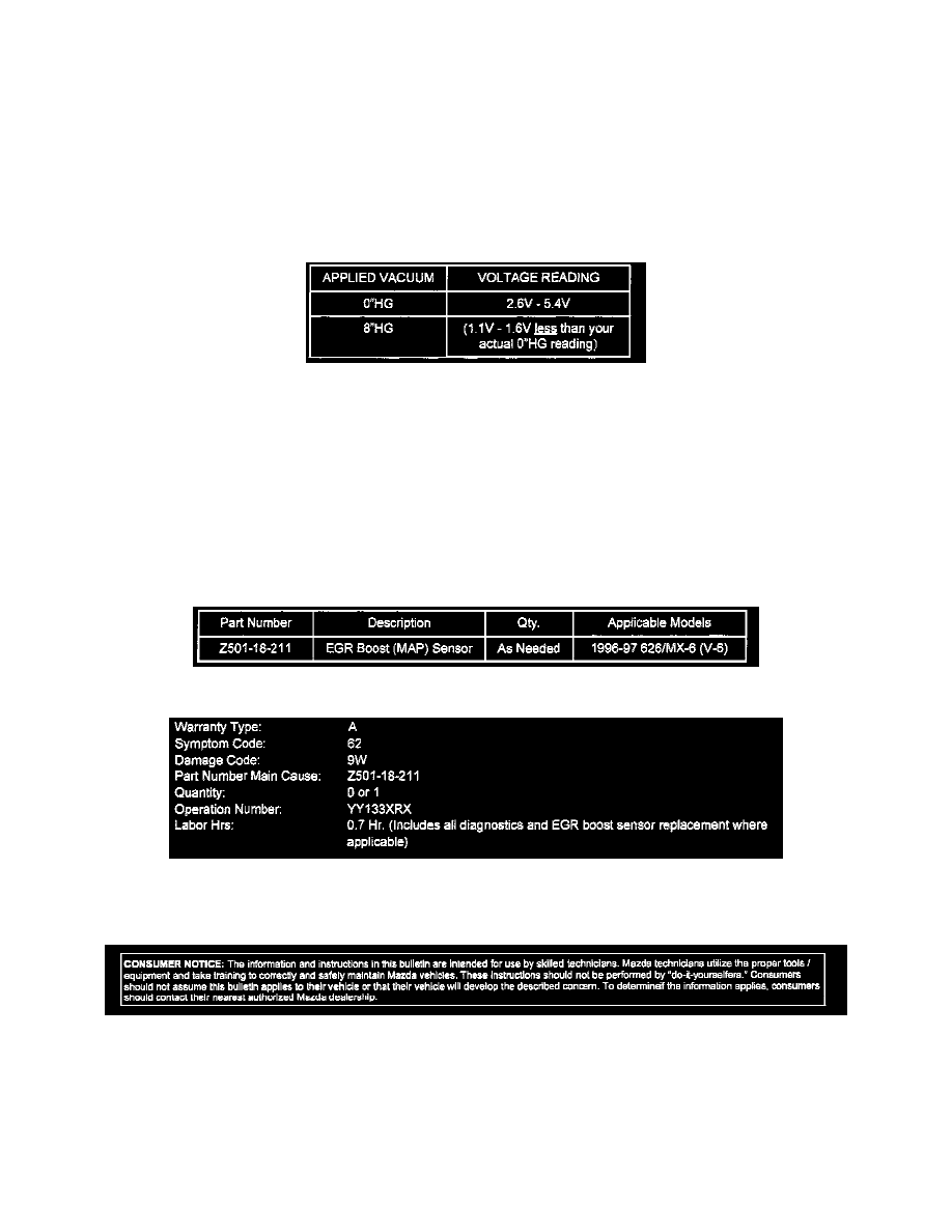
Use a vacuum pump and apply vacuum to the EGR boost sensor according to the table.
5.
Record the voltage. Refer to the table shown.
^
If the voltage readings are not within the specified range replace boost sensor and proceed to step 6.
^
If no problem is found with EGR boost sensor, perform the DTC troubleshooting procedures (refer to Workshop Manual section F2).
6.
Verify the repair by completing the OBD II drive mode (refer to 1995-97 OBD II Service Highlights).
NOTE:
If performing an EGR simulation test in addition to the OBD II drive mode, note that a DTC with format P14** may be set. This is a normal
condition caused by performing the EGR simulation test. Any DTC with format P014** which is set during a simulation test may be ignored and
deleted.
PARTS INFORMATION
WARRANTY INFORMATION
(Applies To Verify Customer Complaints On Vehicles Covered Under Normal Warranty. Refer To The SRT Microfiche For Warranty Term
Information.)
Disclaimer