
929 V6-3.0L SOHC (1989)
EGR Valve Position Sensor: Testing and Inspection
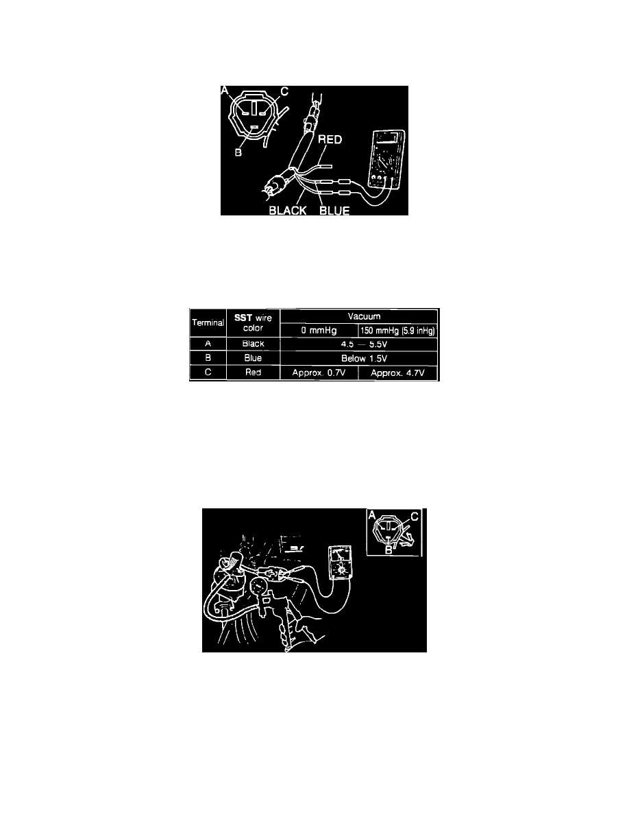
VOLTAGE INSPECTION
1.
Disconnect the EGR position sensor connector.
EGR Position Sensor Terminal Identification
2.
Connect the test adapter (SST Mazda Part# 49 G018 901) between the EGR sensor and the wiring harness.
3.
Disconnect the vacuum hose from the EGR control valve and connect the vacuum pump.
4.
Turn the ignition switch on.
5.
Check the voltage of each terminal in the conditions shown in the table.
EGR Position Sensor Test Chart
6.
If not correct at terminals "A" and "B", check the wiring harness and terminals "2A" and "2C" of the engine control unit.
7.
If not correct at terminal "C", check the wiring harness and terminal "2F" of the engine control unit.
8.
Disconnect the adapter and reconnect the EGR position sensor connector.
RESISTANCE INSPECTION
1.
Disconnect the EGR position sensor connector.
Testing EGR Position Sensor
2.
Disconnect the vacuum hose from the EGR control valve and connect the vacuum pump.
3.
Using an ohmmeter, check the resistance between the terminals as shown when applying vacuum.
TERMINAL RESISTANCE
A - B Approx. 5 KOhm
A - C 0.7 - 5 KOhm
B - C 0.7 - 5 KOhm