
B2300 L4-2.3L (2008)
Horn: Initial Inspection and Diagnostic Overview
Inspection and Verification
1. Verify the customer concern.
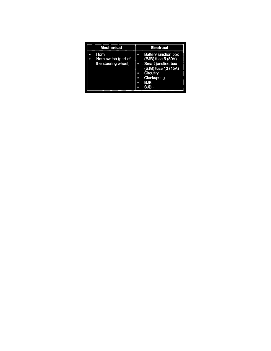
2. Visually inspect the following for obvious signs of mechanical or electrical damage.
Visual Inspection Chart
3. If an obvious cause for an observed or reported concern is found, correct the cause (if possible) before proceeding to the next step.
NOTE: Make sure to use the latest scan tool software release.
4. If the cause is not visually evident, connect the IDS or equivalent tester to the data link connector (DLC) and select the vehicle to be tested from
the IDS or equivalent tester menu.
NOTE: The vehicle communication module (VCM) LED prove-out confirms power and ground from the DLC are provided to the VCM.
5. If the IDS or equivalent tester does not communicate with the VCM:
-
Check the VCM connection to the vehicle.
-
Check the IDS or equivalent tester connection to the VCM.
-
See PINPOINT TEST 7: NO MODULE/NETWORK COMMUNICATION - NO POWER TO THE DIAGNOSTIC TOOL to diagnose no
communication with the scan tool. See: Body and Frame/Body Control Systems/Testing and Inspection/Pinpoint Tests/Pinpoint Test 7: No
Module/Network Communication - No Power to the Diagnostic Tool
6. If the scan tool does not communicate with the vehicle:
-
Verify the ignition key is in the ON position.
-
Verify the scan tool operation with a known good vehicle.
-
See SYMPTOM TROUBLESHOOTING CHART - COMMUNICATIONS NETWORK to diagnose no response from powertrain control
module. See: Body and Frame/Body Control Systems/Testing and Inspection/Symptom Related Diagnostic Procedures
7. Carry out the network test:
-
If the scan tool responds with no communication for one or more modules, see SYMPTOM TROUBLESHOOTING CHART -
COMMUNICATIONS NETWORK. See: Body and Frame/Body Control Systems/Testing and Inspection/Symptom Related Diagnostic
Procedures
-
If the network test passes, retrieve and record the continuous memory diagnostic trouble codes (DTCs).
8. Clear the continuous DTCs and carry out the self-test diagnostics for the SJB.
9. If the DTCs retrieved are related to the concern, see SMART JUNCTION BOX (SJB) DIAGNOSTIC TROUBLE CODE (DTC) INDEX. For all
other DTCs, see DIAGNOSTIC TROUBLE CODE (DTC) INDEX - B, C AND U CODES See: Powertrain Management/Computers and Control
Systems/Testing and Inspection/Diagnostic Trouble Code Descriptions/Troubleshooting/Lighting Systems
10. If no DTCs related to the concern are retrieved, see SYMPTOM TROUBLESHOOTING CHART - HORN. See: Symptom Related Diagnostic
Procedures