
B2300 L4-2.3L (2008)
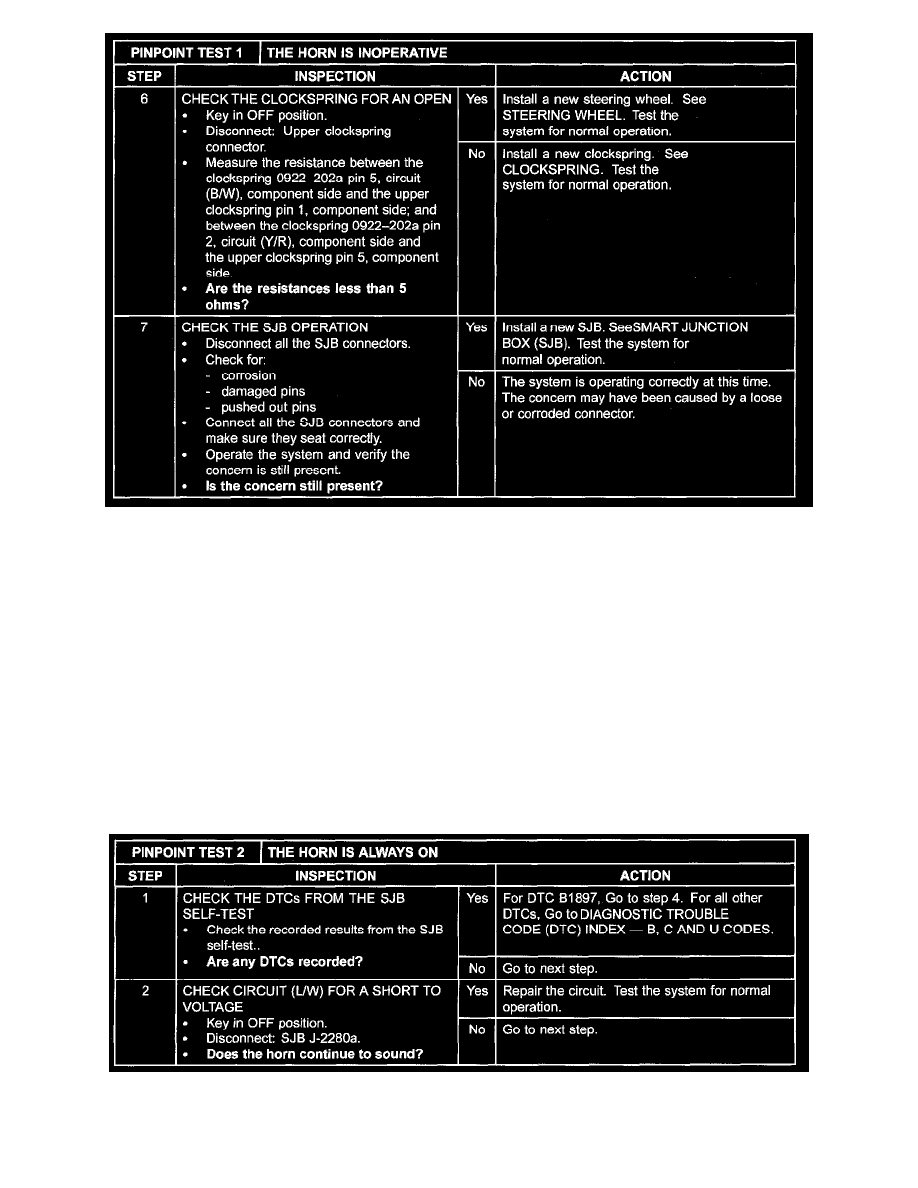
Step 6-Step 7
Pinpoint Test 2
PINPOINT TEST 2: THE HORN IS ALWAYS ON
Normal Operation
The horn relay control voltage and the horn relay switched voltage circuits are supplied by the smart junction box (SJB) fuse 13 (15 A) through circuit
(GY/R). The horn relay (part of the SJB) is controlled by circuit (Y/R) through the clockspring to the horn switch (part of the steering wheel). When the
horn switch is pressed, the horn relay control circuit (Y/R) is grounded through the steering wheel switch harness (part of the steering wheel). The horn
relay is then energized causing voltage to be applied to circuit (B/W), enabling the horn to sound. Ground to the horn is supplied through circuit (B/GY).
This pinpoint test is intended to diagnose the following:
-
Wiring, terminals or connectors
-
Clockspring
-
Horn switch (part of the steering wheel)
-
SJB
Step 1-Step 2