
B2300 L4-2.3L (2008)
Engine Control Module: Component Tests and General Diagnostics
POWERTRAIN CONTROL MODULE (PCM) INSPECTION
CAUTION: The PCM terminal voltages vary with change in measuring conditions and vehicle conditions. Always carry out a total inspection
of the input systems, output systems, and PCM to determine the cause of trouble. Otherwise, a wrong diagnosis will be made.
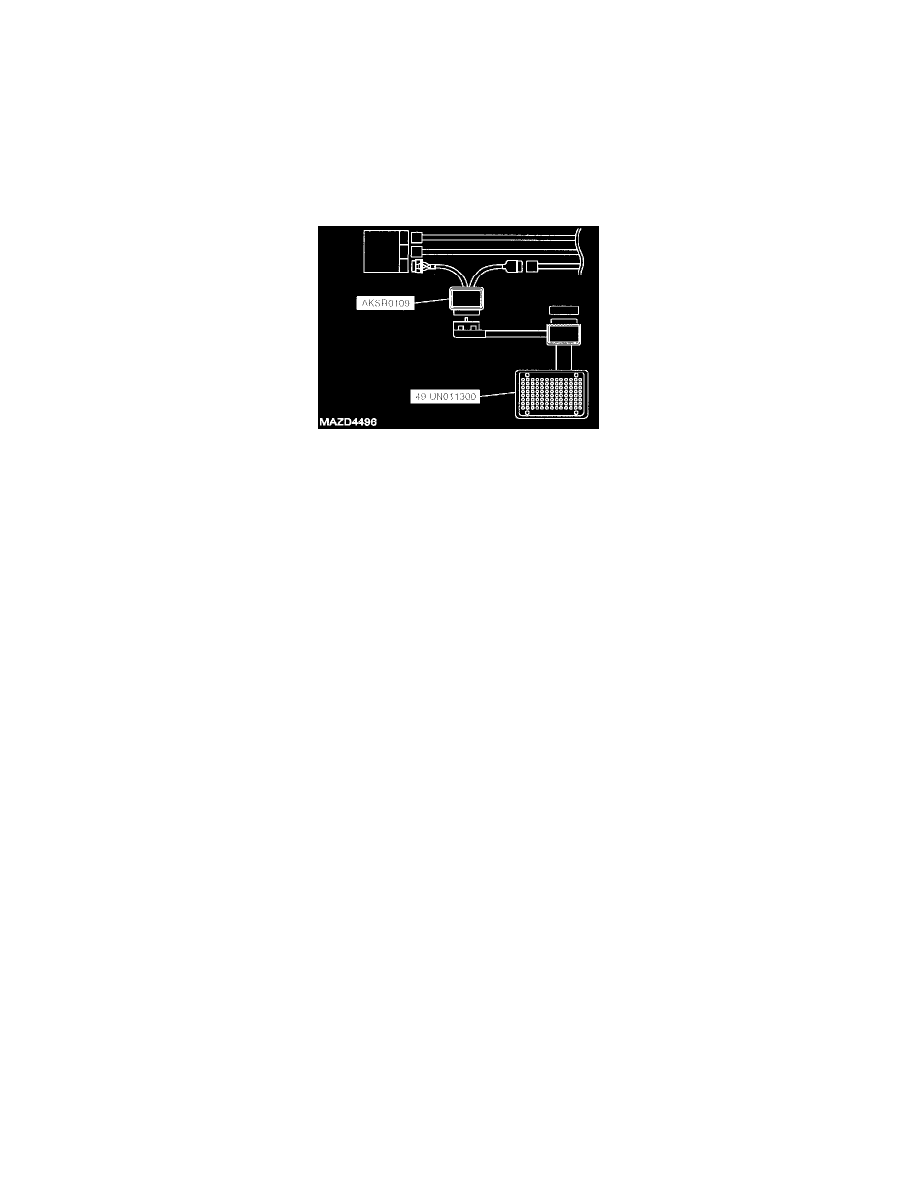
Using SST (104 Pin Breakout Box and PCM Adaptor)
1. Disconnect the battery.
2. Disconnect the PCM connectors.
3. Connect the 104 Pin Breakout Box and the PCM adaptor SST to the PCM.
4. Connect the battery.
5. Measure the voltage at each terminal.
6. If any incorrect voltage is detected, check related systems, wiring harnesses and connectors referring to the possible malfunction in the terminal
voltage list.
Using the SST (IDS or equivalent tester)
1. In the passenger compartment, connect the IDS or equivalent scan tool SST to the data link connector.
CAUTION: The "PID/DATA MONITOR AND RECORD" function is to monitor the calculation value of the input/output signals in the
PCM. Deviation in the value does not always indicate malfunction in the related devices. For inspection of the input/output signals other
than in the link monitor table, check voltage at the applicable PCM terminal by using the 104 Pin Breakout Box.
2. Carry out inspection referring to PID/DATA MONITOR table.
3. If normal output signal cannot be detected when all input signals are normal, replace the PCM.