
B2300 L4-2.3L (2008)
Engine Control Module: Service and Repair
POWERTRAIN CONTROL MODULE (PCM) REMOVAL / INSTALLATION
NOTE:
-
PCM Programming, Vehicle Identification (VID) Block and "As Built Data" for a Replacement PCM: A new PCM will contain the latest strategy
and calibration level for a particular vehicle. However, the VID block will be blank and will need programming. There are two procedures
available: The first is an automatic data transfer from the old PCM to the new PCM and the second is "As Built Data" or manual data entry into the
new PCM:
Once keep alive random access memory (RAM) has been reset, the engine must idle for 15 minutes (actual time varies between strategies) to learn
new idle air trim values
-
Automatic data transfer is performed if the old PCM is capable of communicating. This is done by the use of a scan tool to retrieve data from the
old PCM before removing it from the vehicle. The stored data can now be downloaded to the new PCM after it has been replaced.
-
"As built data" or manual data entry, must be performed if the old PCM is damaged and/or incapable of communicating. Remove and replace the
old PCM. Using a compatible scan tool, select and execute module/parameter reprogramming, referring to the manufacturer user manual. Make
certain that all parameters are included:
-
Failure to properly program tire size in revolutions per mile, (rev/mile = 63,360 divided by the tire circumference in inches) axle ratio, axle
size, anti-lock brake system (ABS) (4WBS or RWABS) 4WD/2WD, and/or manual / electronic shift on the fly (MSOF/ESOF) may result in
DTCs P1635, P1639.
-
You will need the "as built data" to perform this procedure. If you are unable to obtain "as built data" from Mazda's Electronic Service
Information website, you will need to contact the Mazda Technical Assistance Hotline.
Removal Note
1. Retrieve the module configuration. Perform the module configuration retrieval steps of the Programmable module installation procedure. See
PROGRAMMABLE MODULE INSTALLATION.
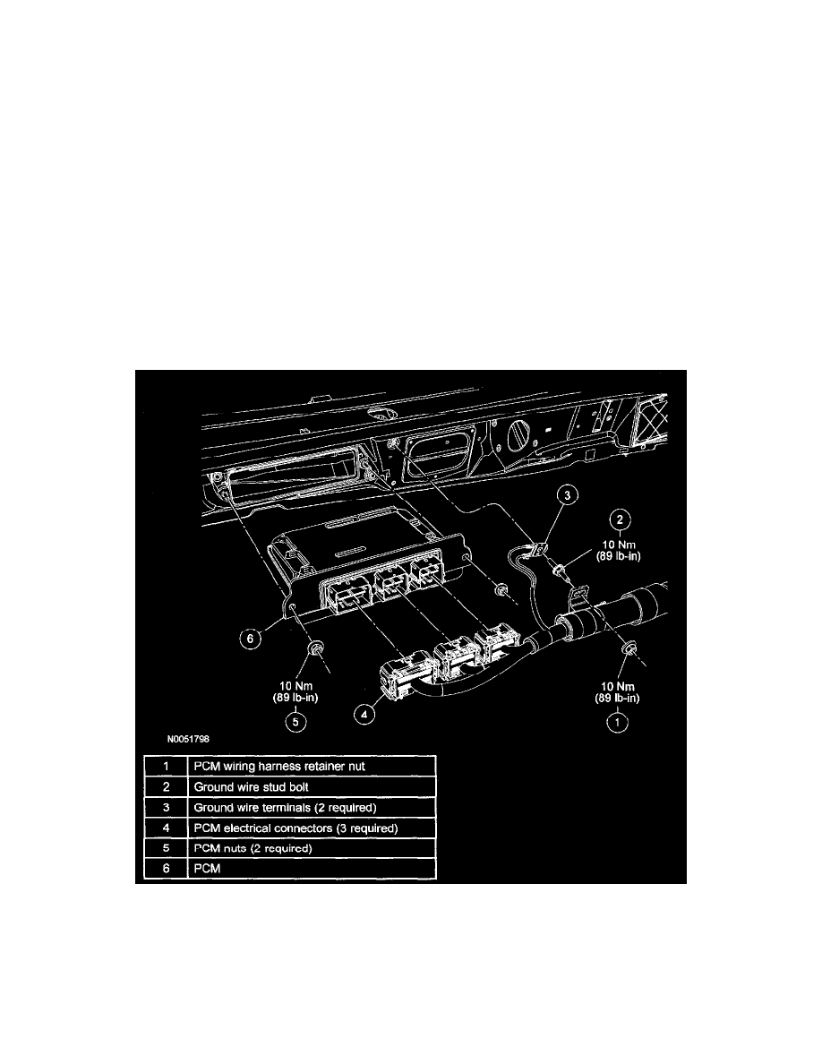
2. Remove the PCM wiring harness retainer nut.
3. Remove the ground wire stud bolt.
4. Disconnect the 3 PCM electrical connectors.
5. Remove the 2 nuts and the PCM.