
B2300 L4-2.3L (2008)
Power Distribution Module: Description and Operation
SMART JUNCTION BOX (SJB)
Principles of Operation
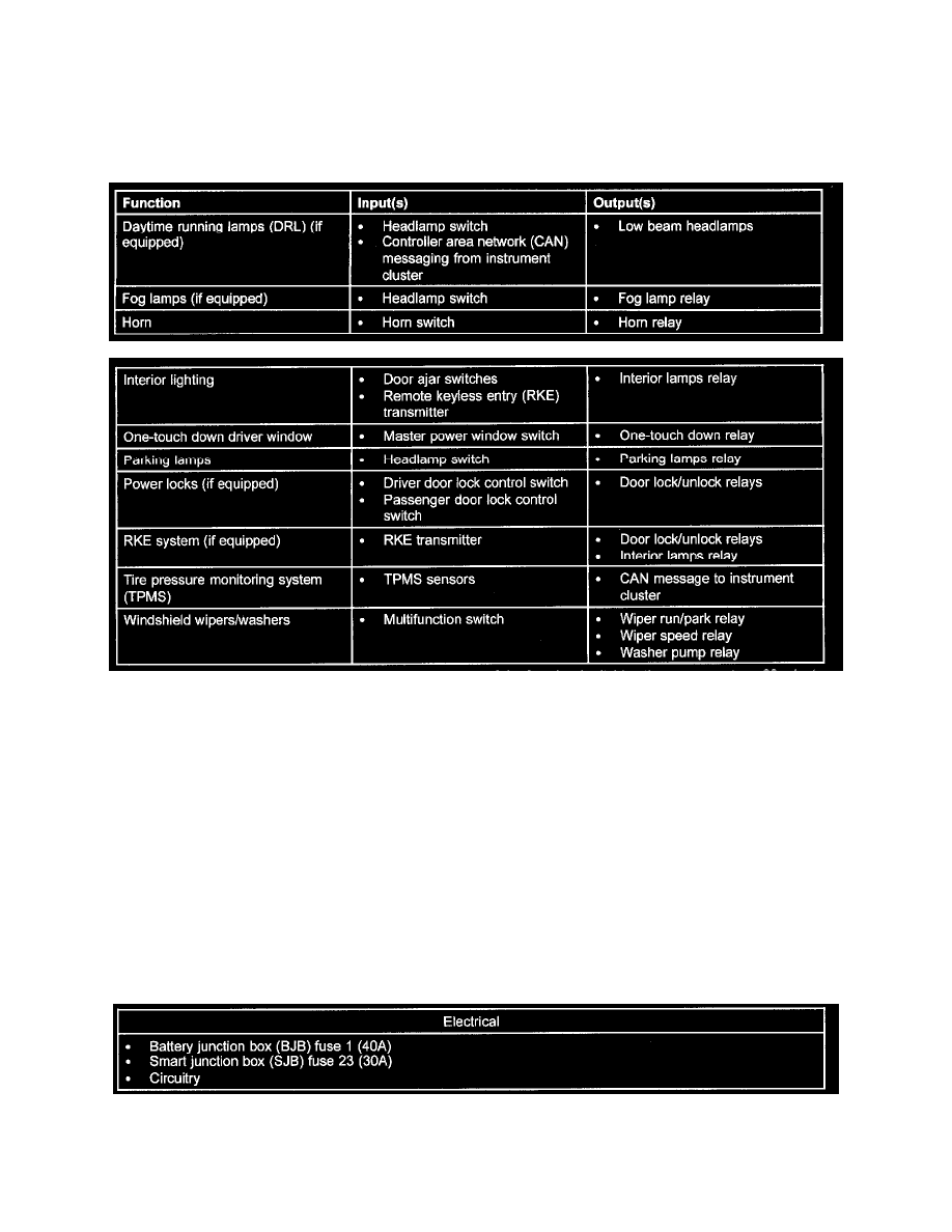
The SJB is a multifunction module that controls many of the vehicle systems. Several SJB functions utilize hardwired inputs and/or outputs. The SJB
controls the following hardwired functions, using the corresponding inputs and outputs:
In addition, the SJB is involved in other vehicle systems through communication over the CAN. For a detailed list of SJB network inputs and outputs,
refer to COMMUNICATIONS NETWORK. Some SJB parameters are programmable. Two types of programmable parameters are available: vehicle
configuration and customer preference. For additional information on programmable parameters, refer to PROGRAMMABLE MODULE
INSTALLATION. See: Body and Frame/Body Control Systems/Testing and Inspection/Initial Inspection and Diagnostic Overview
The SJB utilizes a protective circuit strategy for many of its outputs (for example, the headlamp output circuit). Output loads (current level) are
monitored for excessive current (typically short circuits) and are shut down (turns off the voltage or ground provided by the module) when a fault is
detected. A continuous diagnostic trouble code (DTC) is stored at that time for the fault. The circuit will then reset after an ignition cycle or customer
demand of the function (switching the component on, 30-minute battery saver being energized). When an excessive circuit load occurs several times, the
module shuts down the output until a service procedure is performed. At the same time, the continuous DTC that was stored on the first failure will not
clear by a command to clear the continuous DTCs. The module will not allow this code to be cleared or the circuit restored to normal until a successful
on-demand self-test proves that the fault has been repaired. After the on-demand self-test has successfully completed (no on-demand DTCs present), the
continuous DTC will have been cleared and the circuit function will return.
Inspection and Verification
1. Verify the customer concern.
2. Visually inspect for obvious signs of mechanical or electrical damage.
Visual Inspection Chart
3. If an obvious cause for an observed or reported concern is found, correct the cause (if possible) before proceeding to the next step.