
B2300 L4-2.3L (2008)
Drive/Propeller Shaft: Testing and Inspection
Propeller Shaft Runout and Balance
PROPELLER SHAFT RUNOUT AND BALANCE
1. With the vehicle in neutral, position it on a hoist.
2. Remove the rear wheels and tires. Install the lug nuts to retain the brake drums.
3. Inspect the propeller shaft for damage, undercoating or incorrectly seated U-joints. Rotate the propeller shaft slowly by hand and feel for binding
or end play in the U-joint trunnions. Remove and inspect the slip yoke splines for any galling, dirt, rust or incorrect lubrication. Clean the propeller
shaft or install new U-joints as necessary. Install a new propeller shaft if damaged. After any corrections or new components are installed, recheck
for the vibration at the road test speed.
-
If the vibration is gone, test drive the vehicle.
-
If the vibration persists or the propeller shaft passes visual inspection, measure the propeller shaft runout.
4. Install a dial indicator. Rotate the propeller shaft by turning the axle and measure the runout at the front, the center and the rear of the propeller
shaft
-
If the runout exceeds specifications at the front or center, install a new propeller shaft.
-
If the front and center is within specification, but the rear runout is not, index-mark the rear runout high point and proceed to propeller shaft
balancing in this procedure.
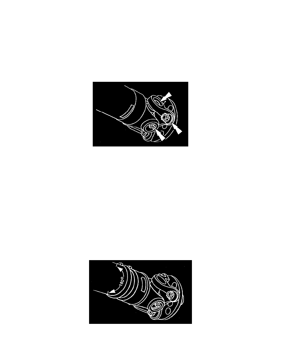
5. Index-mark the propeller shaft to the pinion flange. Disconnect the propeller shaft and rotate it 180 degrees. Reconnect the propeller shaft.
Recheck the runout at the rear of the propeller shaft.
-
If the runout is still over specification, mark the high point and proceed to the next step.
-
If the runout is within specification, check for the vibration at the road test speed. If the vibration is still present, proceed to propeller shaft
balancing in this procedure.
6. Excessive propeller shaft runout can originate in the propeller shaft itself or from the pinion flange. To find the source, compare the 2 high points
previously determined.
-
If the index marks are close together, within 25 mm (1 in), the propeller shaft is eccentric. Install a new propeller shaft
-
If the marks are on opposite sides of the propeller shaft, 180 degrees apart, the slip yoke or pinion flange is responsible. Check the pinion
flange runout. If the pinion flange runout exceeds specifications, a bent pinion is indicated.
-
If the pinion flange and pinion runouts are within specifications, road test and check for the vibration at the road test speed. If the vibration
persists, proceed to propeller shaft balancing in this procedure.
7. Balance the propeller shaft.
(1) Install two stainless steel screw-type hose clamps on the propeller shaft with the clamp screws opposite the mark.
(2) Tighten the hose clamps starting at the pinion yoke end of the propeller shaft.
Warning:
-
Keep hands away from the balance weights while the propeller shaft is rotating.
8. Run the vehicle at baseline speed.