
B2300 Regular Cab 2WD L4-2.3L VIN A (1997)
Case: Service and Repair
Assembly
PROCEDURE
1. Install the 5th/reverse cam lockout plate, referring to the following:
^
5th/reverse cam lockout plate Install the 5th/reverse cam lockout plate and bolts. Tighten to 8 - 10 Nm (6 - 7 ft. lbs.).
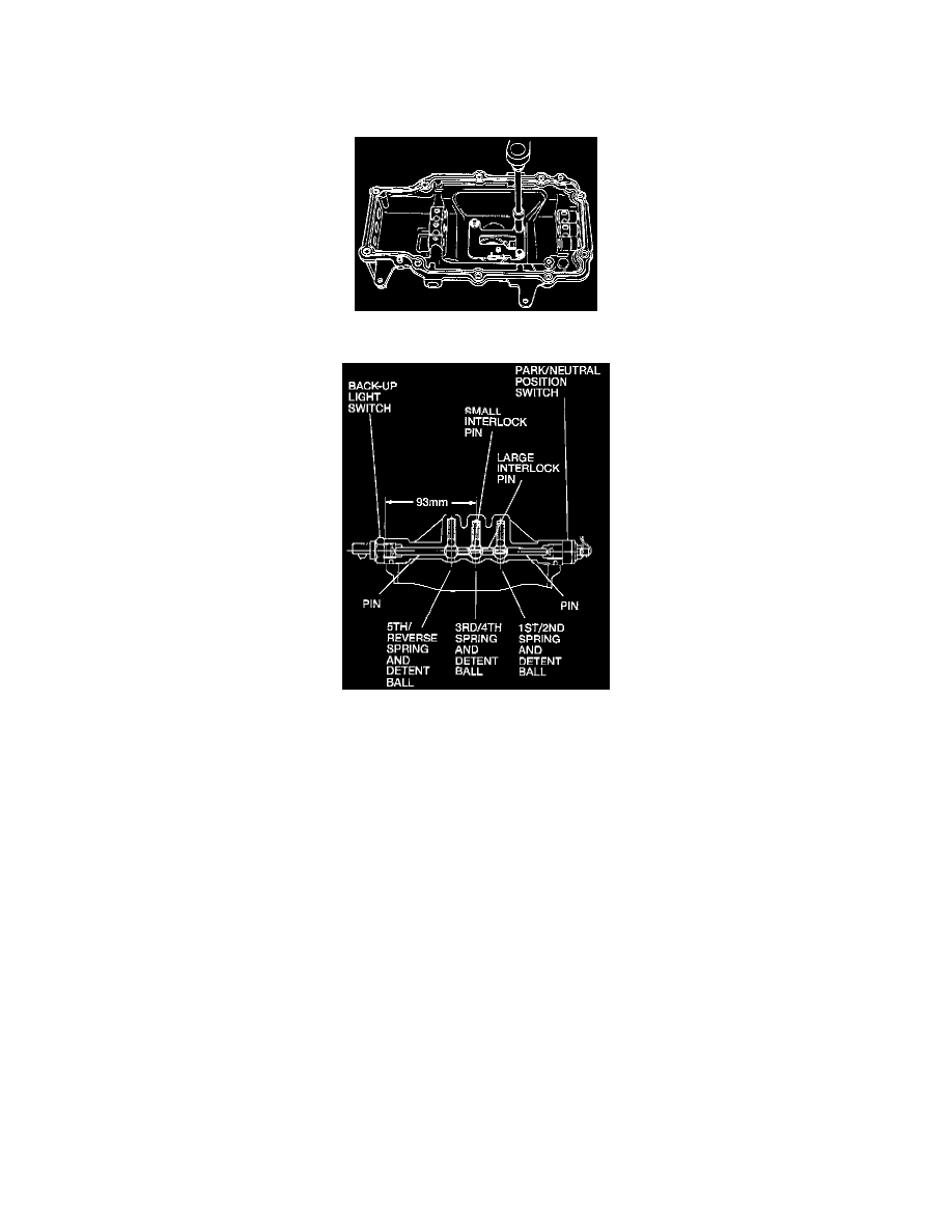
2. Install the 1st/2nd and 3rd/4th interlock pins, referring to the following:
^
Install the large and small pins in their original positions.
3. Install the shift rods, referring to the following:
3rd/4th Shift Rods
1. Position the shift rod into the control case.
2. Position the detent ball and spring into the control case spring seats.
3. Compress the detent ball and spring assembly and push the shift rod into position over the detent ball.
4. Engage the 3rd/4th shift fork with the shift rod.
5. Position the friction device and spring into the control case spring seats.
6. Compress the friction device and spring assembly and push the shift rod into position over the friction device.
7. Install the 3rd/4th shift gate.
8. Install the 3rd/4th shift fork spring interlock pins.
1st/2nd Shift Rods
1. Position the shift rod into the control case.
2. Position the detent ball and spring into the control case spring seats.
3. Compress the detent ball and spring assembly and push the shift rod into position over the detent ball.
4. Engage the 1st/2nd shift fork with the shift rod.
5. Position the friction device and spring into the control case spring seats.
6. Compress the friction device and spring assembly and push the shift rod into position over the friction device.
7. Install the 1st/2nd shift gate.
8. Install the 1st/2nd shift fork spring interlock pins.