
B2300 SE Regular Cab 2WD L4-2.3L VIN A (1997)
Transmission Position Switch/Sensor: Testing and Inspection
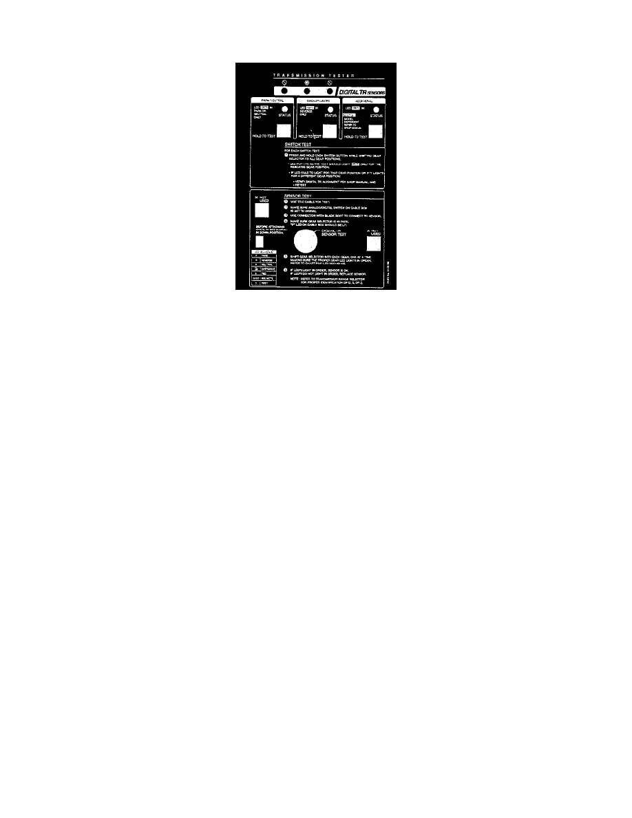
NOTE: The transmission tester allows a technician to operate the electrical portion of the TR sensor.
TRANSMISSION RANGE (TR) SENSOR TESTING USING TRANSMISSION TESTER
1. Perform Preparation and Hook-up procedures.
CAUTION: For resistance checks, be sure that the tester selector switch is set to the DIGITAL TR SENSOR TEST position or damage to the
ohmmeter may result.
2. Sensor tests.
a. Using the transmission tester and Transmission Range (TR) Sensor Cable and Overlay 49 UN01 154, perform TR Sensor test based on the
DTCs that were displayed.
NOTE:
-
Select and connect the appropriate cable to the tester and then black connector of cable to TR sensor.
-
Be sure switch on tester is in the down position.
b. Perform services as indicated by the pinpoint tests. Always retest and road test vehicle after any service.
3. Test procedures-gear position.
a. Place transmission range selector lever into Park.
b. Ensure that the ANALOG/DIGITAL switch on TR sensor cable is set to DIGITAL.
c. Move the transmission range selector lever through all ranges.
d. Monitor the LEDs, located on the cable, in each gear position. The LED should illuminate RED for the appropriate range selected.
e. If the LED for the applicable gear range position fails to illuminate RED or if it lights for a position other than the gear selected:
-
Verify test cable connections
-
Verify transmission shift linkage for proper adjustment.
-
Verify TR sensor for proper adjustment.
4. Voltage tests-park/neutral, backup lamp and optional circuit.
a. Set test selector switch to the DIGITAL TR SENSOR TEST position.
b. Press and HOLD each button while moving the gearshift lever through EACH gear position.
c. Monitor each LED.
d. The status LED should indicate RED only in the indicated position. Refer to overlay.
NOTE: LED will turn RED when the circuit closes and turn OFF when the circuit is open.
e. If the LED does NOT indicate RED in the desired position or indicates RED in another position, first verify Transmission Range (TR) sensor
alignment and then retest.
5. Perform tester removal.