
B3000 V6-3.0L (2007)
1. Verify the customer concern.
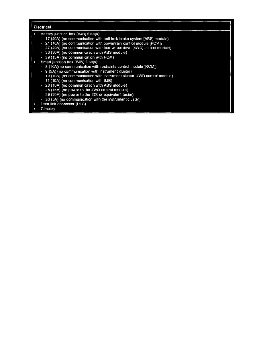
2. Visually inspect the following for obvious signs of electrical damage.
3. If an obvious cause for an observed or reported concern is found, correct the cause (if possible) before proceeding to the next step.
NOTE: Make sure to use the latest IDS or equivalent tester software release.
4. If the cause is not visually evident, connect the IDS or equivalent tester to the DLC.
NOTE:
-
The vehicle communication module (VCM) LED prove-out confirms power and ground from the DLC are provided to the VCM.
-
If the IDS or equivalent tester does not communicate with the VCM.
-
Check the VCM connection to the vehicle.
-
Check the IDS or equivalent tester connection to the VCM.
-
See PINPOINT TEST 8: NO MODULE/NETWORK COMMUNICATION - NO POWER TO THE DIAGNOSTIC TOOL See: Pinpoint
Tests/Communication Network/Pinpoint Tests/Pinpoint Test 8: No Module/Network Communication - No Power to the Diagnostic Tool,
to diagnose no power to the IDS or equivalent tester.
NOTE: During the network test, the IDS or equivalent tester will first attempt to communicate with the PCM, after establishing
communication with the PCM, the IDS or equivalent tester will then attempt to communicate with all other modules on the vehicle.
5. Carry out the network test.
-
If the network test passes, retrieve and record the continuous memory DTCs and proceed to Step 6.
-
If the network test fails, see SYMPTOM TROUBLESHOOTING CHART - COMMUNICATIONS NETWORK, See: Symptom Related
Diagnostic Procedures/Symptom Troubleshooting Chart/Communication Network to identify the module not communicating.
6. If the DTCs retrieved are related to the concern, go to that module's Diagnostic Trouble Code (DTC) Index. For all other DTCs, see
DIAGNOSTIC TROUBLE CODE (DTC) INDEX - B, C AND U CODES.
7. If no DTCs related to the concern are retrieved, see SYMPTOM TROUBLESHOOTING C HART - COMMUNICATIONS NETWORK. See:
Symptom Related Diagnostic Procedures/Symptom Troubleshooting Chart/Communication Network
Body System
BODY SYSTEM DIAGNOSIS AND TESTING
Inspection and Verification
Leaks
NOTE: Trim removal will reveal the location of most leaks
1. Remove trim or carpet in the general area of the leak.
2. Road test or water test the vehicle. Use leak check powder to help locate leak paths around weather-strips.
3. Inspect for a dust pattern around the area in question.
4. Inspect for water paths near and above the area in question.
5. Some leaks can be located by placing bright light under the vehicle, removing trim or carpet as needed, and inspecting the interior of the body at
joints and weld lines.