
B3000 V6-3.0L (2007)
Step 7
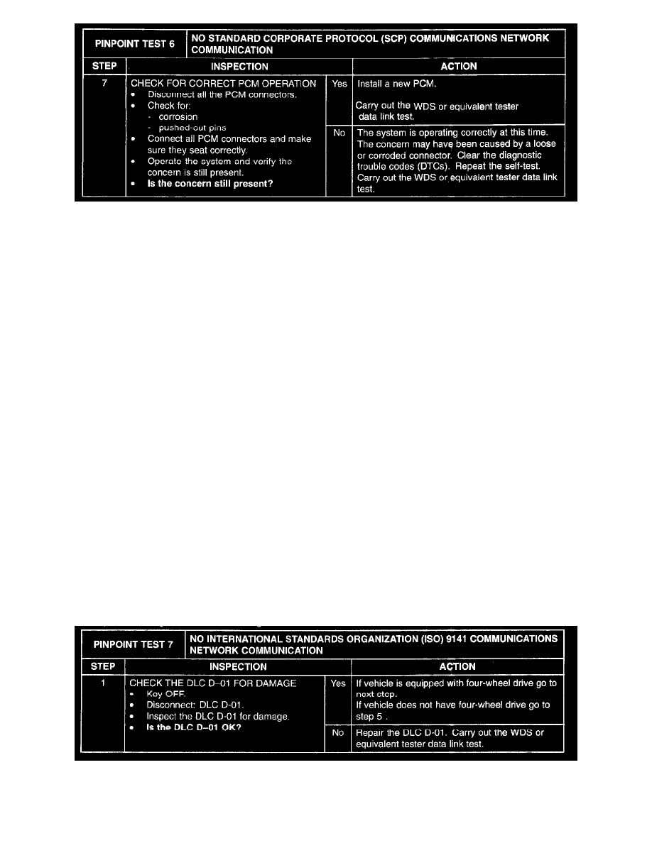
Pinpoint Test 7
PINPOINT TEST 7: NO INTERNATIONAL STANDARDS ORGANIZATION (ISO) 9141 COMMUNICATIONS NETWORK
COMMUNICATION
Normal Operation
The restraints control module (RCM), four-wheel drive (4WD) control module, smart junction box (SJB), and the anti-lock brake system (ABS) module
communicate with the WDS or equivalent tester through the IS09141 communication network circuit (LB/W). Check circuit (LB/W) between the
networked modules and the data link connector (DLC) D-01. If the IS09141 communication network circuit is open, communication to the module in
question is not possible. If the circuit is shorted to ground or shorted to voltage, the entire network goes down and communication to all modules is not
possible. If, after individual checks of each circuit leading to a module show resistance values less than 5 ohms, and no in-line connector issues are
present, the data link diagnostics test must be run with the module in question disconnected. If the data link diagnostics test passes with the module in
question disconnected, it is the source of the concern and should be removed and a new module installed.
Possible Causes
-
ISO 9141 communication network circuit (LB/W) open, short to ground or short to voltage
-
DLC D-01
-
RCM 0810-101
-
4WD control module 0318-02 (if equipped)
-
SJB J-2280d
-
ABS module 0413-102
-
RCM
-
4WD control module (if equipped)
-
SJB
-
ABS module
NOTE: The ISO 9141 network diagnostics requires de-power of the air bag system when disconnecting the RCM 0810-101. When key ON occurs to
carry out the data link diagnostic test, diagnostic trouble codes (DTCs) may be stored in the RCM. These DTCs should be cleared when network
diagnostics are completed.
CAUTION: Use the correct probe adaptor(s) when making measurements. Failure to use the correct probe adaptor(s) may damage the connector.
Step 1