
B3000 V6-3.0L (2007)
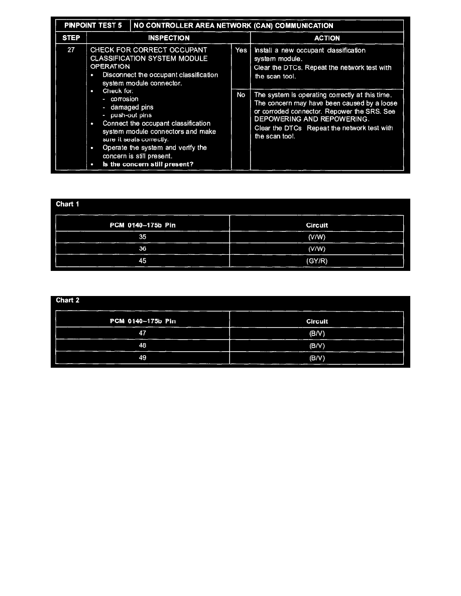
Step 27
Chart 1
Chart 2
Normal Operation
The PCM communicates with the scan tool through the high speed controller area network (HS-CAN). Circuits (W/L) (HS-CAN +) and (W) (HS-CAN
-) provide the network connection to the PCM. The PCM shares the HS-CAN with the four wheel drive (4WD) control module, the restraints control
module (RCM), the occupant classification sensor module, the smart junction box (SJB), and the instrument cluster. Circuits (V/W) and (GY/R) provide
voltage, and redundant circuit (B/V) provides ground.
Possible Causes
-
Fuse
-
Circuit (V/W) open
-
Circuit (GY/R) open
-
Circuit (B/V) open
-
CAN data plus circuit (W/L) open, short to ground, or short to voltage
-
CAN data minus circuit (W) open, short to ground, or short to voltage
-
CAN data plus circuit (W/L) and CAN data minus circuit (W) shorted together
-
DLC D-01
-
PCM
-
RCM
-
Occupant classification sensor module
-
Instrument cluster
-
SJB