
B3000 V6-3.0L (2007)
-
Carry a live air bag module with the air bag and trim cover pointed away from your body. This will reduce the risk of injury in the event of an
accidental deployment.
-
Do not set a live air bag module down with the trim cover face down. This will reduce the risk of injury in the event of an accidental deployment.
-
After deployment, the air bag surface can contain deposits of sodium hydroxide, a product of the gas gene flint combustion that is irritating to the
skin. Wash your hands with soap and water afterwards.
-
Never probe the connectors on the air bag module. Doing so can result in air bag deployment, which can result in personal injury.
-
Air bag modules with discolored or damaged trim covers must be installed new, not repainted.
-
To reduce the risk of personal injury, do not use any memory saver devices.
NOTE:
-
The air bag warning lamp illuminates when the restraints control module (RCM) fuse is removed and the ignition switch is ON. This is normal
operation and does not indicate a supplemental restraint system (SRS) fault.
-
The SRS must be fully operational and free of faults before releasing the vehicle to the customer.
-
A repair is made by installing a new part only. If the new part does not correct the condition, install the original part and perform the diagnostic
procedure again.
1. Depower the SRS. See DEPOWERING AND REPOWERING.
2. Remove the driver air bag module. See DRIVER AIR BAG MODULE.
NOTE: Make sure the wheels are in the straight-ahead position.
3. Remove the steering wheel. See STEERING WHEEL.
4. Remove the ignition lock cylinder. See IGNITION LOCK CYLINDER - FUNCTIONAL.
5. Remove the 2 screws and position the hood release handle out of the way.
6. Remove the screws from the lower steering column opening finish panel. Then pull out to release the retaining clips and remove the lower steering
column opening finish panel.
7. Remove the 4 bolts and remove the lower steering column opening finish panel reinforcement.
8. If equipped, remove the tilt wheel handle and shank.
9. Remove the 3 screws and the lower steering column shroud.
10. Position the upper steering column shroud up enough to access the clockspring retaining clips.
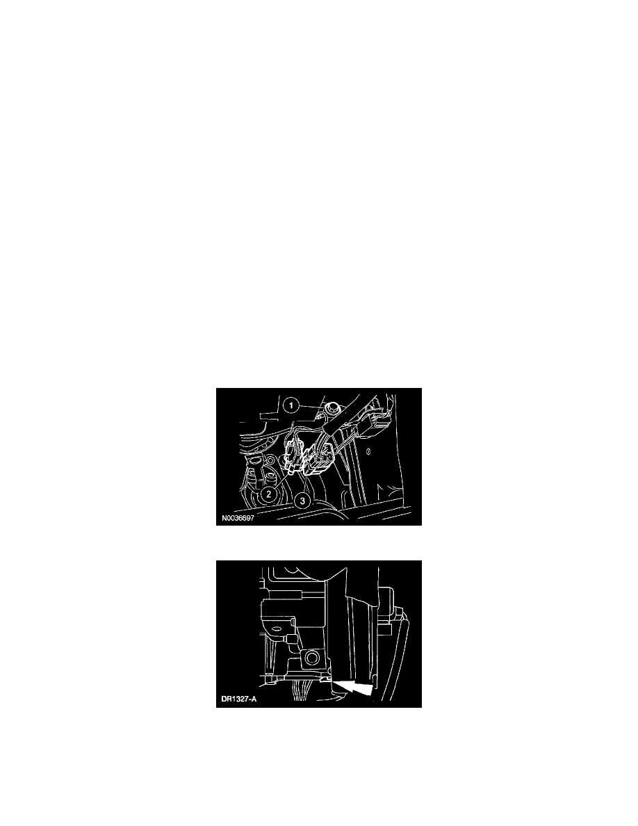
11. Detach the clockspring wire harness from the wiring retainer.
12. Remove the clockspring electrical connectors.
1. Remove the clockspring ground wire bolt.
2. Release the pin-type retainer and disconnect the clockspring electrical connector.
3. Release the pin-type retainer and disconnect the clockspring electrical connector.