
B3000 4WD V6-3.0L OHV (1995)
^
If still present, refer to section "F" of the workshop manual for troubleshooting and repair information.
REPAIR PROCEDURE
Procedure "A"
Visually inspect the vapor return hoses coming from the canister.
^
Replace, repair or reconnect hoses as required.
Procedure "B"
1.
Inspect the wiring harness leading to the canister purge solenoid for damage resulting from contact with the power steering bracket.
^
If damaged, replace the entire connector assembly.
NOTE:
Use the Purge Solenoid Service Kit and it's enclosed instruction sheet to splice the wiring pigtails. DO NOT attempt to repair or replace the wire
without the service kit.
^
Fasten the wire assembly to the fender apron routing it away from the power steering pump assembly.
NOTE:
Use the wire routing template supplied in the kit.
2.
Inspect the wiring harness terminals at the canister purge solenoid and the purge flow sensor for damage.
^
If damaged, replace the entire connector assembly.
NOTE:
Use the Purge Solenoid Service Kit and/or the Purge Flow Sensor Service Kit and each enclosed instruction sheet. DO NOT attempt to repair or
replace the terminals without the service kit If either the canister purge solenoid or purge flow sensor requires replacement, all components (hose,
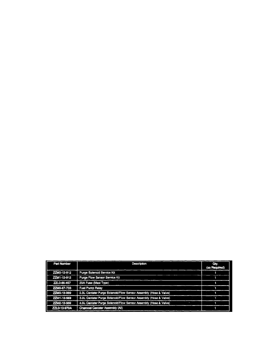
purge valve, flow sensor) must be replaced as an assembly. Refer to the Parts Information below.
3.
Remove the hose and valve assembly.
4.
Arrange a clean piece of paper on a flat surface.
5.
Tap the canister hose (port side of the sensor) on the paper and inspect the surface for charcoal particles that may be caught in the valve and hose
assembly.
^
If particles are noticed, replace the valve and hose assembly and the charcoal canister.
^
If no particles are found, refer to the workshop manual for diagnostic and repair information.
8.
Verify repair.
Procedure "C"
Inspect the fuel pump fuse (yellow 20A maxi type) in the engine compartment main fuse/relay block. Refer to section Z1 of the BETM for location.
If the fuse is blown, check the fuel pump relay (in the same fuse/relay block) according to section F of the workshop manual. Repair as necessary.
PARTS INFORMATION