
B3000 4WD V6-3.0L OHV (1995)
Transmission Position Switch/Sensor: Testing and Inspection
Transmission Range (TR) Sensor Testing Using
Transmission Tester
The transmission tester allows a technician to operate the electrical portion of the TR sensor.
1. Perform Preparation and Hook-up procedures.
Caution: For resistance checks, be sure that the tester selector switch is set to the TR SENSOR TEST position or damage to the ohmmeter may
result.
2. Resistance/continuity tests.
-
Using a digital volt-ohmmeter, the transmission tester and Transmission Range (TR) Sensor Cable 49 UNO1 147 or equivalent, perform TR
Sensor test based on the DTCs that were displayed.
-
Perform services as indicated by the pinpoint tests. Always retest and road test vehicle after any service.
3. TR sensor resistance tests.
-
Set ohmmeter to 1000 ohm range.
-
Connect the positive lead of the ohmmeter to the TR/MLP jack.
-
Connect the negative lead of the ohmmeter to the SIG RTN jack.
-
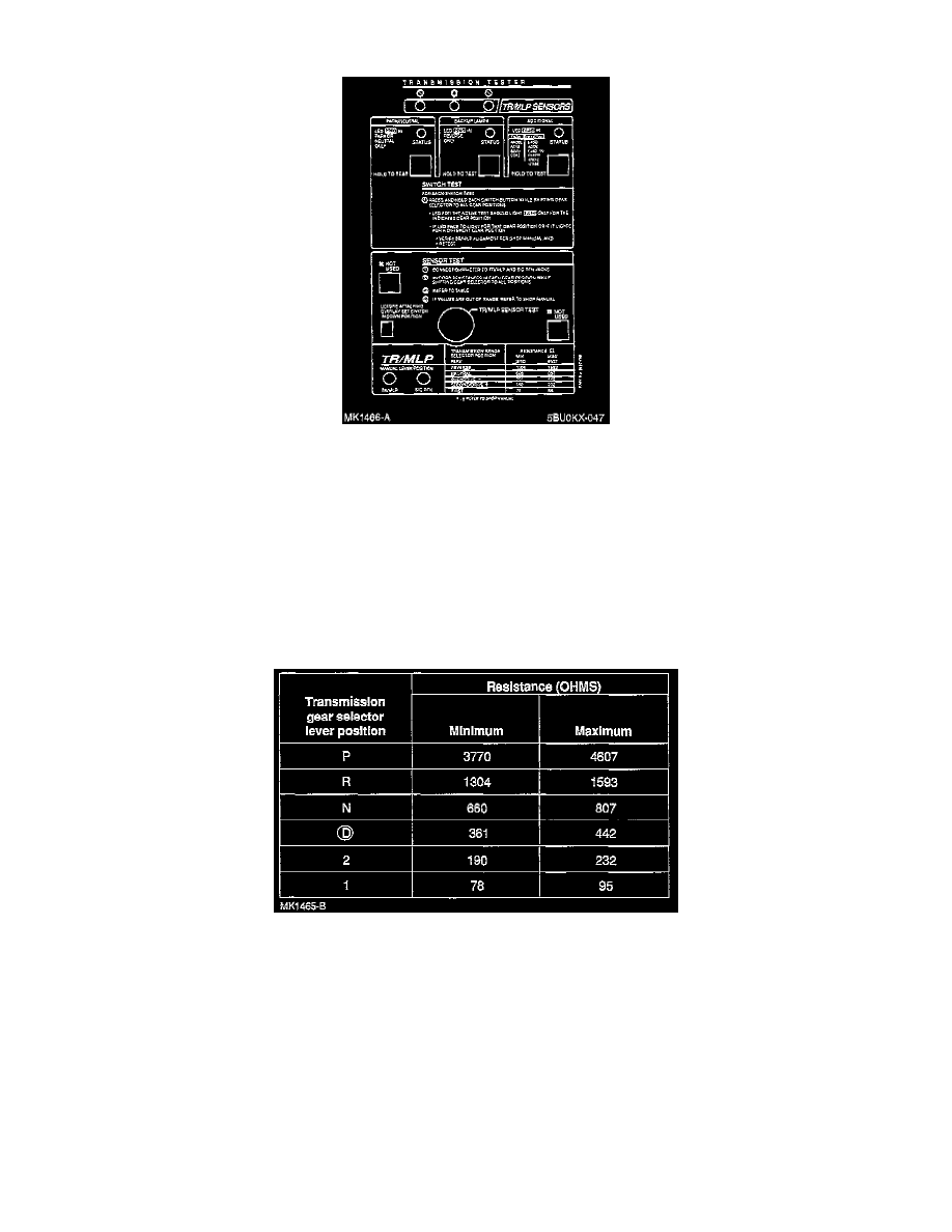
Move transmission gearshift selector lever into each gear position.
-
Record resistance at each position.
-
Refer to the following chart for values.
-
If out of range, perform TR Sensor test.
4. Voltage tests-park/neutral, backup lamp and optional circuit.
-
Set tester selector switch to the TR SENSOR TEST position.
-
Press and HOLD each button while moving the gear-shift lever through EACH gear position.
-
Monitor each LED.
-
The status LED should indicate RED only in the indicated position. Refer to overlay.
Note: LED will turn RED when the circuit closes and turn OFF when the circuit is open.