
B3000 DS Cab Plus 2WD V6-3.0L OHV (2001)
Interior Lighting Relay: Testing and Inspection
Testing of an ISO relay can be accomplished through the use of three No. 10 (or larger gauge) jumper wires and a multimeter.
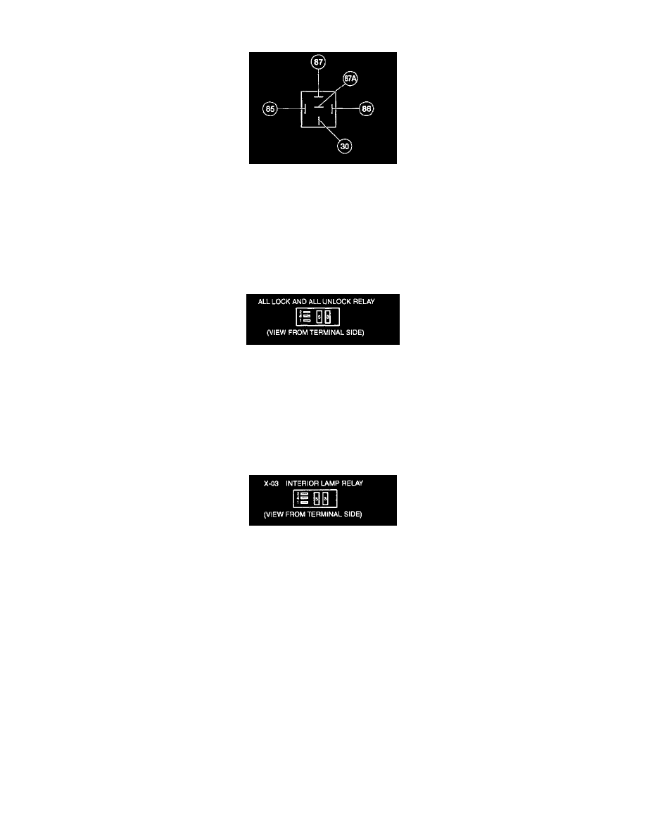
Driver Unlock Relay
Check for the continuity between terminal 85 and all other terminals. If the resistance is 5 ohms or less between terminal 85 and any other terminal,
replace the relay. If the resistance is greater than 5 ohms, continue with the test. Use two jumper wires to connect relay terminals 86 and 30 directly to
the positive battery terminal. Check for voltage at terminal 87A. If battery voltage is not indicated, replace the relay. If battery voltage is indicated,
connect a third jumper wire to terminal 85, and ground the jumper wire to a known good ground. Check for voltage at terminal 87. If battery voltage is
not indicated, replace the relay.
All Lock And All Unlock Relays
Perform this test when directed to in the diagnostic pinpoint tests.
1. Measure resistance between terminal 2 and terminals 1, 3, 4 and 5. If resistance is 5 ohms or less between terminal 2 and any other terminal,
replace the relay. If resistance is greater than 5 ohms, go to step 2.
2. Use two jumper wires to connect terminals 1 and
3. directly to the positive battery terminal. Measure voltage at terminal 4. It there is no battery voltage, replace the relay. If there is battery voltage go
to step 3.
3. Connect a third jumper wire to terminal 2 and a known good ground Measure voltage at terminal 5. If there is no battery voltage, replace the relay.
Perform this test when directed.
1. Measure resistance between terminal 2 and terminals 1, 3, 4 and 5. If resistance is 5 ohms or less between terminal 2 and any other terminal,
replace the relay. If resistance is greater than 5 ohms, go to step 2.
2. Use two jumper wires to connect terminals 1 and 3 directly to the positive battery terminal. Measure voltage at terminal 4. If there is no battery
voltage, replace the relay. If there is battery voltage go to step 3.
3. Connect a third jumper wire to terminal 2 and a known good ground. Measure voltage at terminal 5. If there is no battery voltage, replace the relay
.