
B3000 DS Regular Cab 2WD V6-3.0L OHV (2002)
Courtesy Lamp: Initial Inspection and Diagnostic Overview
NOTE: The generic electronic module (GEM) must be reconfigured upon installation. Refer to diagnostic tool help screen on the configuration card to
program axle ratio and fire size.
1. The interior lighting system is a generic electronic module (GEM) controlled system.
2. Verify the customer concern by operating the interior lighting system.
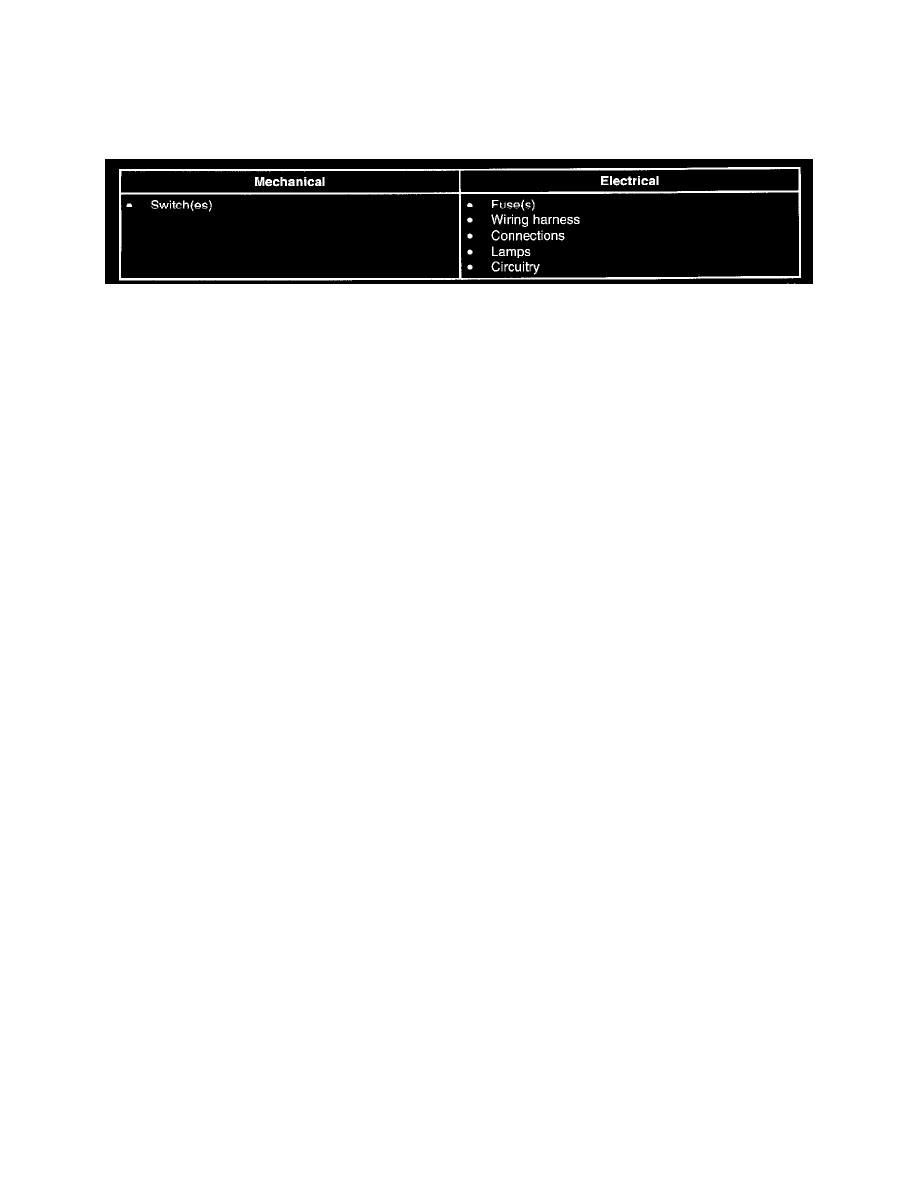
3. Visually inspect for obvious signs of mechanical and electrical damage. Refer to the chart.
4. It the concern remains after the inspection, connect the diagnostic tool to the data link connector (DLC) located beneath the instrument panel and
select the vehicle to be tested from the diagnostic tool menu. If the diagnostic tool does not communicate with the vehicle:
-
check that the program card is correctly installed.
-
check the connections to the vehicle.
-
check the ignition switch position.
5. If the diagnostic tool still does not communicate with the vehicle, refer to the diagnostic tool manual.
6. If the DTCs retrieved are related to the concern, refer to the GEM Diagnostic Trouble Code (DTC) Index to continue diagnostics.
7. If no DTCs related to the concern are retrieved, refer to the Symptom Troubleshooting Chart to continue diagnostics.