
B3000 SE Regular Cab 4WD V6-3.0L OHV (1998)
Control Module: Diagram Information and Instructions
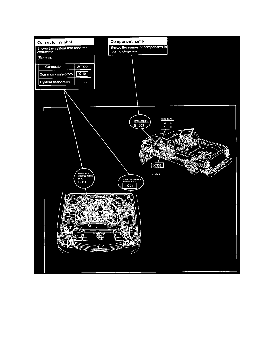
Routing Diagram
Routing Diagram
^
The routing diagram shows where electrical components are on the system circuit diagram by call out line and connector symbols.
Harness Description
Description Of Harness ........................................................................................................................................................................................... Symbol
Main .............................................................................................................................................................................................................................. (MA)
Engine Control Sensor ................................................................................................................................................................................................. (ECS)
Dash Panel To Headlamp Jct...................................................................................................................................................................................... (DPHJ)
Rear Lamp ...................................................................................................................................................................................................................... (RL)
Battery ............................................................................................................................................................................................................................... (B)