
B4000 2WD V6-4.0L OHV (1994)
Camshaft Position Sensor: Testing and Inspection
Component
NOTE:
-
Testing the Camshaft Position Sensor is accomplished by checking the power supply to the Camshaft Position Sensor and the Camshaft Position
Sensor (output) signal to the Powertrain Control Module (PCM). If the PCM and related circuit wiring test OK, then the Camshaft Position Sensor
can be judged as the faulty component in the system links.
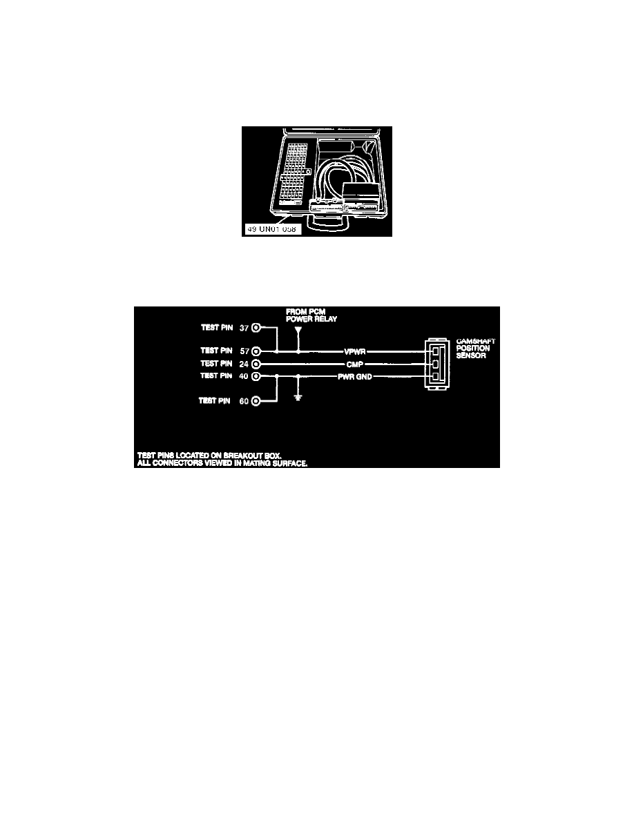
Special Service Tool (SST)-Break Out Box (Used For Voltage Pin Tests)
INSPECTION
-
Connect the Special Service Tool (SST) "Break Out Box" to the PCM.
Camshaft Position Sensor Test Connections
-
Check for proper voltage signals at PCM terminal No.24 under the following conditions.
-
Key On engine Off--11.6 Volts.
-
Engine Idle (HOT)--5.8 Volts.
-
Driving Vehicle 48 km/h (30 mph)--6.5 Volts.
-
Driving Vehicle 88 km/h (55 mph)--6.9 Volts.
-
If readings are correct then the Camshaft Position Sensor is operating properly.
-
If the readings indicate zero then the wiring between PCM terminal No.24 and the Camshaft Position Sensor should be checked and repaired
as necessary.
-
If the above circuit is OK then the power supply to the Camshaft Position Sensor should be checked.
-
If the power supply to the Camshaft Position Sensor is OK then the sensor itself can be suspect as the faulty part of the circuit.
-
Refer to Camshaft Position Sensor Diagnostic Trouble Code (DTC) 214 for other circuit test inspections.
See: Computers and Control Systems/Testing and Inspection/Diagnostic Trouble Code Tests and Associated Procedures/Powertrain
Management/DTC 214