
B4000 4WD V6-4.0L OHV (1995)
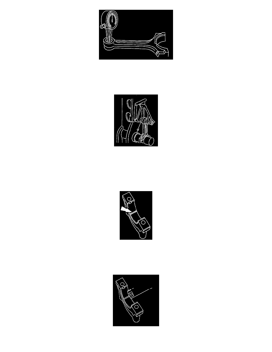
3. Measure the bushing bore diameter of the connecting rod. Verify the diameter is within specification. Refer to Specifications.
See: Specifications
4. Measure the connecting rod bend on a suitable alignment fixture. Follow the instructions of the fixture manufacturer. Verify the bend measurement
is within specification. Refer to Specifications.
See: Specifications
5. Measure the connecting rod twist on a suitable alignment fixture. Follow the instructions of the fixture manufacturer. Verify the measurement is
within specification. Refer to Specifications.
See: Specifications
Connecting Rod Oil Clearance Inspection
NOTE: The crankshaft connecting rod journals must be within specification to check the connecting rod bearing journal clearance.
1. Position a piece of Plastigage across the bearing surface.
2. Install and tighten to specification; refer to Specifications. Remove the connecting rod bearing cap; refer to Engine Disassembly/Assembly.
See: Service and Repair/Engine Disassembly and Assembly
NOTE: Do not turn the crankshaft during this step.
3. Measure the Plastigage to get the connecting rod bearing journal clearance. The Plastigage should be smooth and flat. A changing width indicates