
B4000 Regular Cab 4WD V6-4.0L OHV (1997)
^
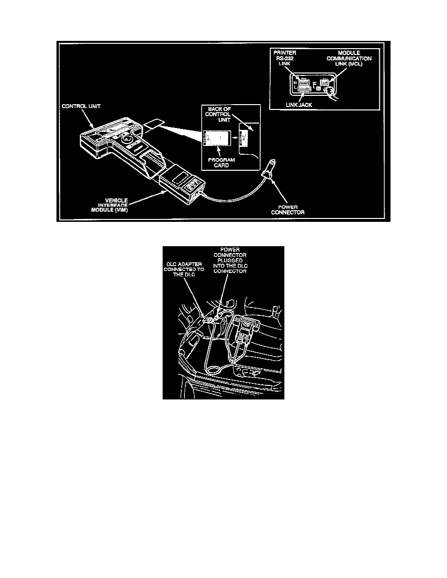
Module communication link (MCL)
^
Link jack
2. The program card containing all control information necessary to diagnose the GEM system is inserted into the back of the NGS control unit.
Connecting NGS Tester to the Vehicle
Preferred Method of Diagnostic and Electrical Hookup
1. Confirm that program card is inserted into back of control unit.
2. Connect data link connector (DLC) adapter to the link jack on NGS Tester.
3. Connect DLC adapter to vehicle DLC.
Alternate Power Hookup
NOTE
^
The following connections are for electrical power supply only. The NGS Tester must be connected to the DLC to perform diagnostics.
Battery Power Hookup Adapter
1. Plug power cable connector into battery power hookup adapter.
2. Connect red adapter clip to positive battery post and black adapter clip to negative battery post.