
B4000 SE Regular Cab 4WD V6-4.0L OHV (1999)
Drive/Propeller Shaft: Testing and Inspection
DRIVELINE VIBRATION
Driveline vibration exhibits a higher frequency and lower amplitude than does high-speed shake. Driveline vibration is directly related to the speed of
the vehicle and is usually noticed at various speed ranges. Driveline vibration can be perceived as a tremor in the floorpan or is heard as a rumble,
hum, or boom. Driveline vibration can exist in all drive modes, but may exhibit different symptoms depending upon whether the vehicle is
accelerating, decelerating, floating, or coasting. Check the driveline angles if the vibration is particularly noticeable during acceleration or
deceleration, especially at lower speeds. Driveline vibration can be duplicated by supporting the axle upon a hoist or upon jack stands, though the
brakes may need to be applied lightly in order to simulate road resistance.
1. Raise the vehicle promptly after road testing. Use a twin-post hoist or jack stands to prevent tire flatspotting. Engage the drivetrain and accelerate
to the observed road test speed to verify the presence of the vibration. If vibration is not evident, check the nondriving wheels with a wheel
balancer to rule out imbalance as a possible cause. If required, balance the non-driving wheels and repeat the road test. If vibration is still evident,
proceed to Step 2.
2. Mark the relative position of the drive wheels to the wheel lugs. Remove the wheels. Install all the lug nuts in the reversed position and repeat the
road speed acceleration. If the vibration is gone, refer to the runout procedure
If vibration persists, proceed to Step 3.
3. Inspect the propeller shaft(s) for signs of physical damage, missing balance weight, undercoating, improper seating, wear and binding universal
joints. Clean the propeller shaft and replace the universal joints or replace the propeller shaft if damaged. Check the index marks (paint spots) on
the rear of the propeller shaft and rear companion flange. If these marks are more than one-quarter turn apart, disconnect the propeller shaft and
re-index to align the marks as closely as possible. After any corrections are made, recheck for vibration at the road test speed. If vibration is gone,
reinstall the wheels and road test. If vibration persists, proceed to Step 4.
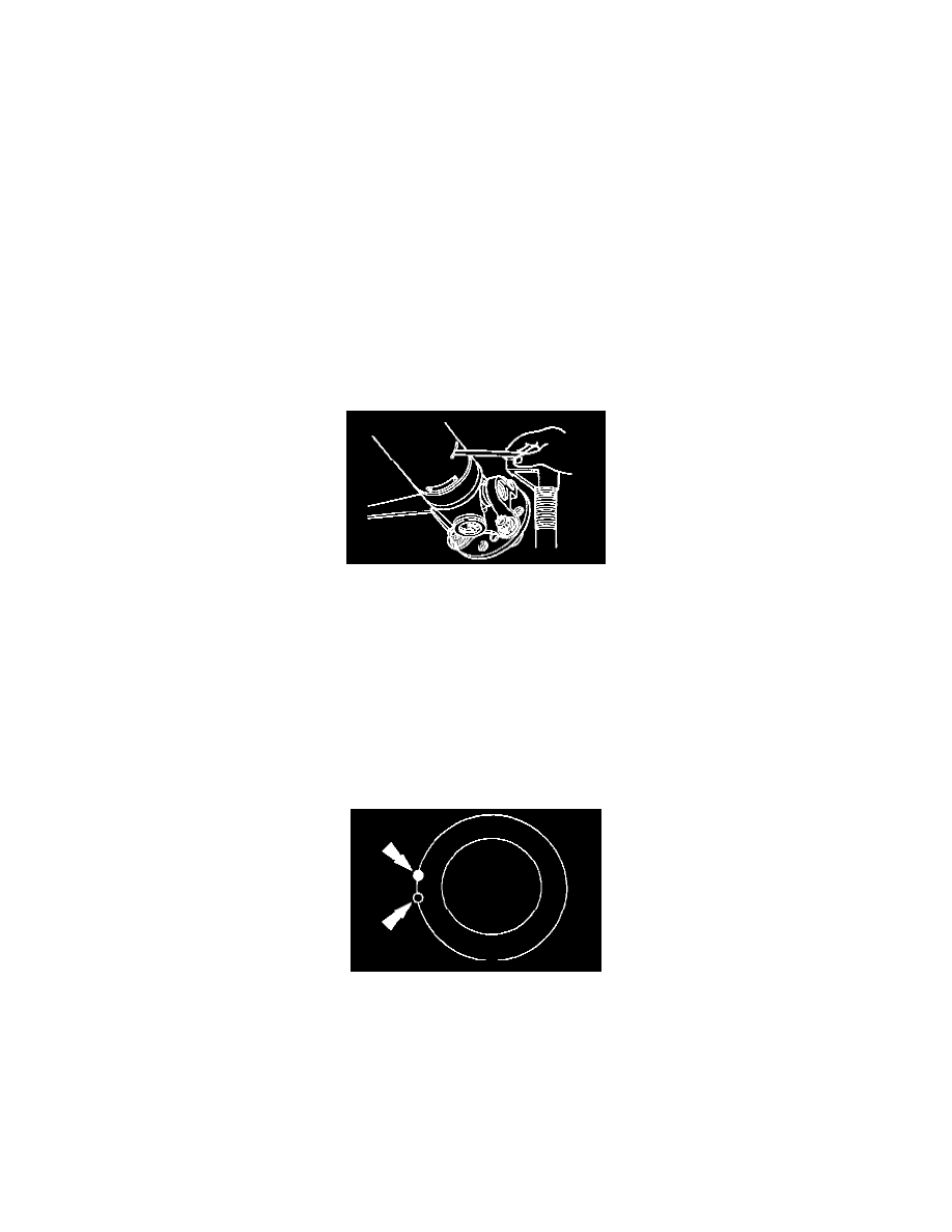
4. Raise the vehicle on a hoist and remove the wheels. Rotate the propeller shaft by turning the axle and measure the runout at the front, the center,
and the rear of the propeller shaft with the indicator. If runout exceeds 0.89 mm (0.035 inch) at the front or center, the propeller shaft must
be replaced. If the front and center are within this limit, but the rear runout is not, mark the rear runout high point and proceed to Step 5. If the
runout is within the limits at all points, proceed to Step 7.
Note: Check the universal joints during re-indexing. If a universal joint feels stiff or gritty, replace the universal joints.
5. Scribe alignment marks on the propeller shaft and the rear companion flange. Disconnect the propeller shaft, rotate it one-half turn, and reconnect
it. Circular companion flanges can be turned in one-quarter increments to fine tune the runout condition; halfround companion flanges are limited
to two positions. Check the runout at the rear of the propeller shaft. If it is still over 0.89 mm (0.035 inch), mark the high point and proceed to
Step 6. If runout is no longer excessive, check for vibration at the road test speed. If vibration is still present, re-index the propeller shaft slip yoke
on the transmission output shaft one-half turn and road test the vehicle. If vibration persists, proceed to Step 7.
6. Excessive propeller shaft runout may originate in the propeller shaft itself or in the axle companion flange. To determine which, compare the two
high points marked in Steps 4 and 5. If the marks are close together, within about 25 mm (1 inch), the shaft must be replaced and the vehicle road
tested.