
B Series Truck L4-2184cc 2.2L 2200 (1988)
EGR Valve Position Sensor: Testing and Inspection
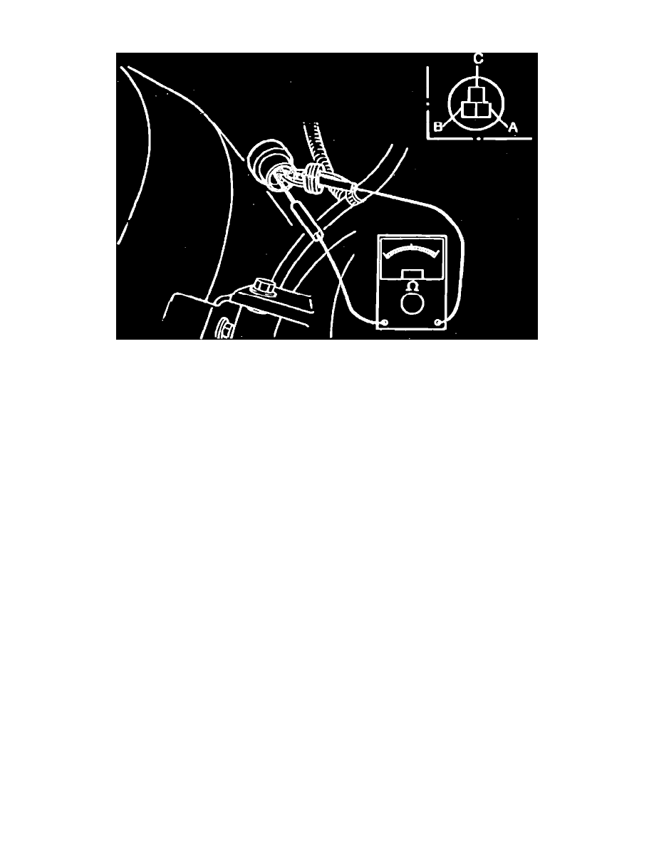
Fig. 22 EGR Position Sensor Connector Terminal Identification. Turbo
1.
Test voltage as follows:
a. Remove rubber boot from connector.
b. Disconnect vacuum hose from EGR control valve and, using suitable vacuum pump, apply vacuum to valve.
c. Turn ignition switch to ``On''.
d. Check voltage of each terminal, Fig. 22. Voltage at terminal C (626) or black/green wire terminal (B2200) should be approximately .7 volt
with no vacuum applied and approximately 4.7 volts with 5.9 inches Hg vacuum applied. Voltage at black/light green wire terminal should be
less then 1.5 volts regardless of vacuum applied. Voltage at green/yellow wire terminal should be 4.5---5.5 volts regardless of vacuum
applied.
e. If voltage reading is incorrect at black/light green and green/yellow wire terminals, check wiring harness and the EGI control unit.
f.
If voltage is incorrect at black/green wire terminal, check resistance of sensor, then the wiring harness and EGI control unit.
g. Reinstall rubber boot.
2.
Check resistance as follows:
a. Disconnect electrical connector at sensor.
b. Remove rubber boot from connector.
c. Check resistance between terminals while applying 0---5.9 inches Hg of vacuum to EGR control valve. Resistance between black/ light green
and and green/yellow wire terminals should be 5k ohms, resistance between black/green and green/yellow wire terminals should be 0---5.5k
ohms and resistance between black/green and black/light green wire terminals should be .7---6k ohms.