
B Series Truck 2WD L4-2184cc 2.2L 2200 2-bbl (1990)
Electronic Brake Control Module: Testing and Inspection
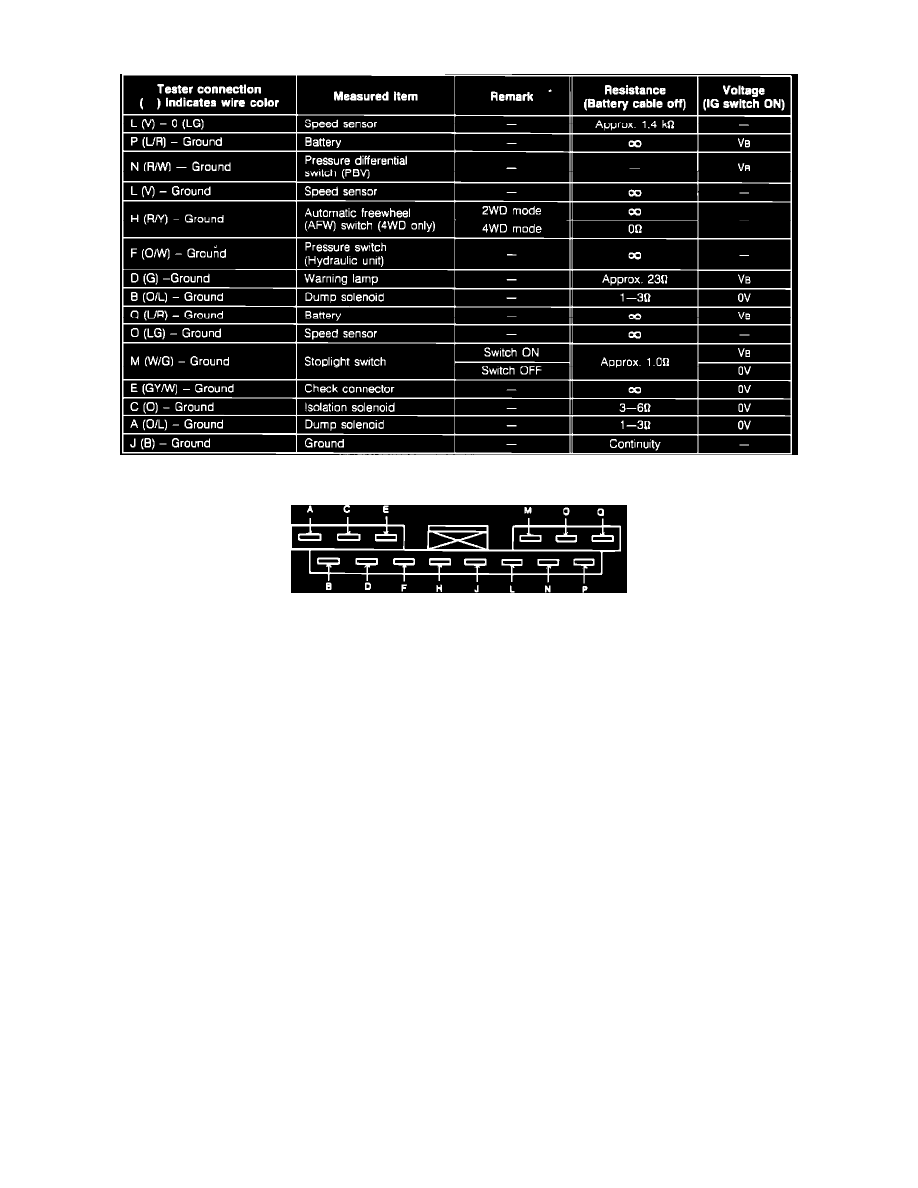
Fig. 66 Control Unit Voltage/resistance Specification.
Fig. 67 Control Unit Connector Terminal Identification
When checking resistance at control unit terminals, always disconnect battery cable.
1.
Remove rear side trim A, then disconnect harness connector from control unit.
2.
Check control unit harness connector terminals for voltage or resistance, Figs. 66 and 67.