
CX-7 AWD L4-2.3L Turbo (2008)
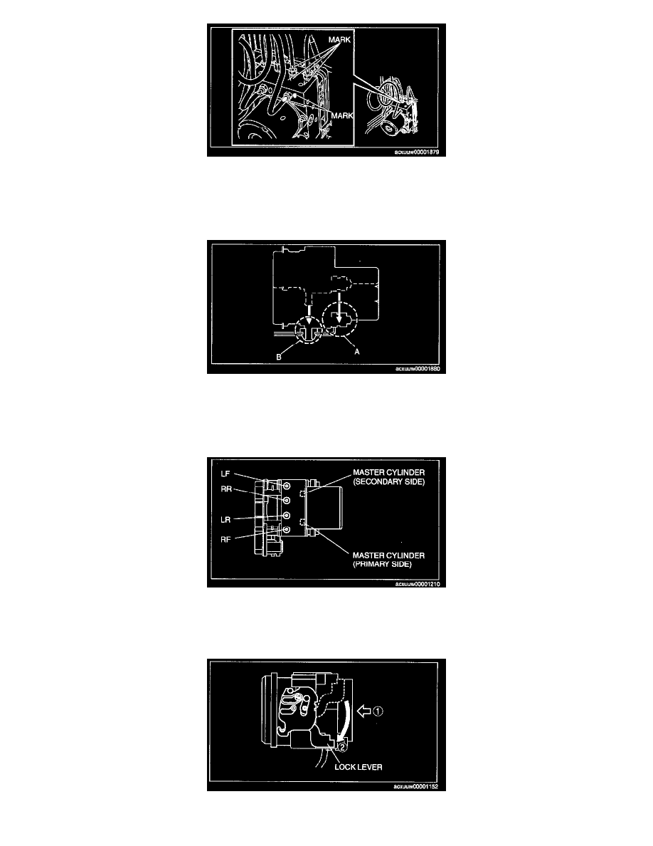
1. Place an alignment mark on the brake pipe and DSC HU/CM
2. Apply protective tape to the connector to prevent brake fluid from entering.
3. Remove the brake pipe.
DSC HU/CM Installation Note
1. Install the rubber mount on DSC HU/CM section A to the bracket as shown in the figure.
2. Install DSC HU/CM section B to the bracket.
3. Install the nuts to DSC HU/CM section A and tighten them.
Brake Pipe Installation Note
1. Align the marks made before removal and install the brake pipe to the DSC HU/CM and brake pipe joint referring to the figure.
2. Tighten the brake pipe to the specified torque using the commercially available flare nut wrench.
DSC HU/CM Connector Installation Note
1. After connecting the connector, verify that the lock lever is completely pushed in.