
CX-7 AWD L4-2.3L Turbo (2008)
Valve Clearance: Testing and Inspection
VALVE CLEARANCE INSPECTION/ADJUSTMENT [L3 WITH TC]
Valve Clearance Inspection
1. Disconnect the negative battery cable.
2. Remove the splash shield (RH).
3. Remove the charge air cooler.
4. Remove the high pressure fuel pump.
5. Remove the ignition coils.
6. Disconnect the wiring harness.
7. Remove the ventilation hose.
8. Remove the cylinder head cover.
9. Measure the valve clearance.
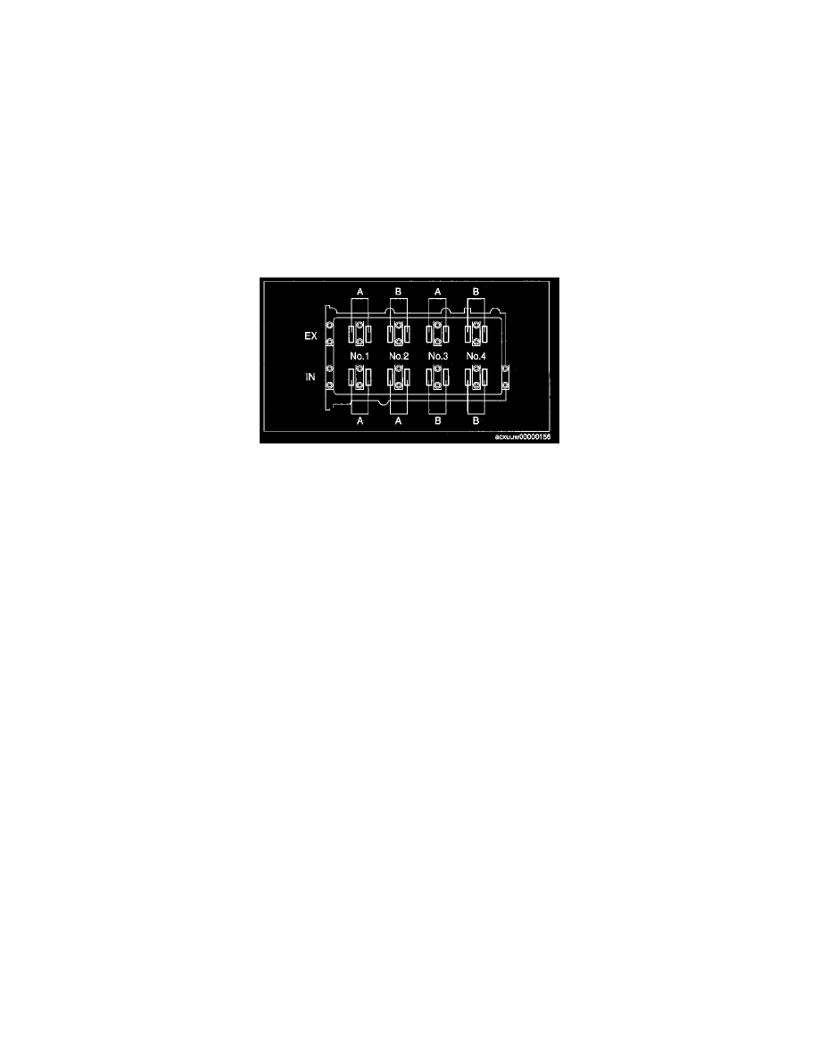
1) Rotate the crankshaft clockwise so that the No.1 cylinder is at TDC of the compression stroke.
2) Measure the valve clearance of location A shown in the figure.
Standard valve clearance [Engine cold]
IN: 0.22-0.28 mm (0.0087-0.011 in)
EX: 0.27-0.33 mm (0.011-0.012 in)
3) If it is not within the specification, replace the tappet and adjust the valve clearance to the median value of the standard.
Note
^
Make sure to note down the measured values for choosing the suitable replacement tappets.
4) Rotate the crankshaft clockwise 360° so that the No.4 cylinder is at TDC of the compression stroke.
5) Measure the valve clearance of location B shown in the figure.
Standard valve clearance [Engine cold]
IN: 0.22-0.28 mm (0.0087-0.011 in)
EX: 0.27-0.33 mm (0.011-0.012 in)
6) If not within the specification, replace the tappet and adjust the valve clearance to the median value of the standard.
10. Install the cylinder head cover.
11. Install the ventilation hose.
12. Connect the wiring harness.
13. Install the ignition coils.
14. Install the high pressure fuel pump.
15. Install the charge air cooler.
16. Install the splash shield (RH).
17. Connect the negative battery cable.