
CX-7 FWD L4-2.3L Turbo (2010)
Vehicle condition
-
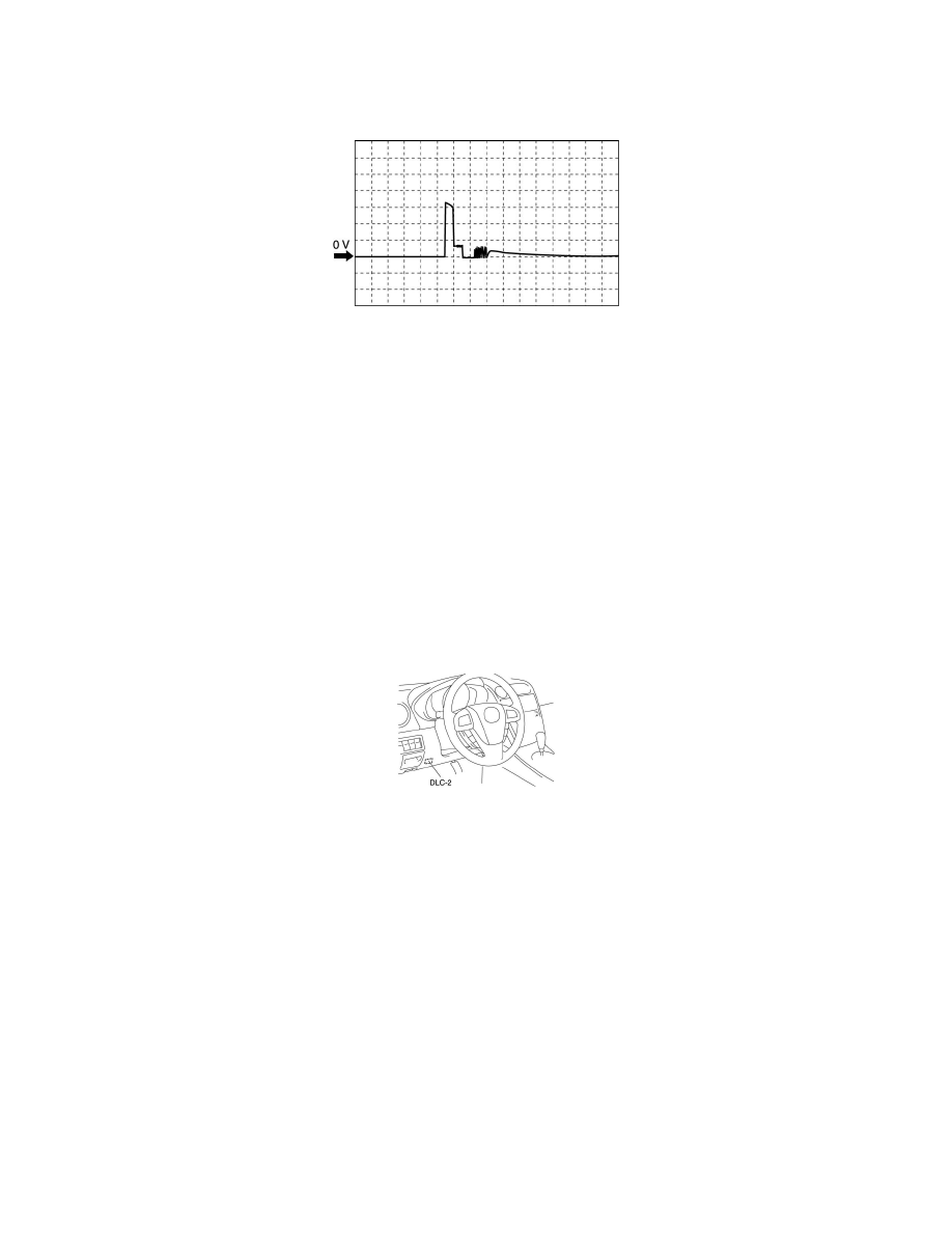
Idle after warm up (no load, P/S off, A/C off)
Fuel injection control (+)
PCM terminals
-
Fuel injection No.1, No.4: 2BG (+)-body ground (-)
-
Fuel injection No.2, No.3: 2BH (+)-body ground (-)
Oscilloscope setting
-
20 V/DIV (Y), 400 ms/DIV (X), DC range
Vehicle condition
-
Idle after warm up (no load, P/S off, A/C off)
Using the M-MDS
NOTE:
-
PIDs for the following parts are not available on this model. Perform the specific inspections for the following parts:
-
CMP sensor (See See: Camshaft Position Sensor/Testing and Inspection.)
-
Main relay
1. Connect the M-MDS to the DLC-2.
2. Turn the ignition switch to the ON position.
3. Measure the PID value.
-
If PID value is not within the specification, follow the instructions in the "Inspection item" column.
NOTE:
-
The PID/DATA MONITOR function monitors the calculated value of the input/output signals in the PCM. Therefore, an output device
malfunction is not directly indicated as a malfunction of the monitored value for the output device. If a monitored value of an output device is
out of specification, inspect the monitored value of the input device related to the output control.
-
For input/output signals except those of the monitoring items, use a voltmeter to measure the PCM terminal voltage.
-
The simulation items that are used in the ENGINE CONTROL SYSTEM OPERATION INSPECTION are as follows.
-
ACCS, ALTF, ARPMDES, EVAPCP, EVAPCV, FAN_DUTY, FAN_DUTY2, FP, IMRC, INJ_1, INJ_2, INJ_3, INJ_4, SEGRP, TEST,
VT DUTY1 Wt, WGC
PID/DATA monitor table (reference)