
CX-7 FWD L4-2.3L Turbo (2010)
Tire Pressure Sensor: Initial Inspection and Diagnostic Overview
MALFUNCTIONING WHEEL UNIT IDENTIFICATION
NOTE:
-
The tire pressure monitoring system (TPMS) does not identify the location of the malfunctioning wheel unit on the vehicle (RF, LF, LR, RR). The
TPMS identifies each wheel unit as No.1, No.2, No.3 and No.4. In order to identify the location of the wheel unit, perform the following
procedure.
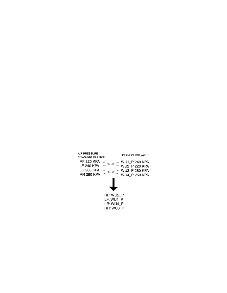
1. Adjust the air pressure as follows:
-
RF: 220 kPa {2.2 kgf/cm2, 32 psi}
-
LF: 240 kPa {2.4 kgf/cm2, 35 psi}
-
LR: 260 kPa {2.6 kgf/cm2, 38 psi}
-
RR: 280 kPa {2.8 kgf/cm2, 40 psi}
2. Switch the ignition to off.
3. Connect the M-MDS to the DLC-2.
4. Switch the ignition to ON.
5. Drive the vehicle at a speed of 25 km/h {15.5 mph} or more for 2 min or more.
6. Select the following PIDs using the M-MDS, and monitor them.
-
WU1_P
-
WU2_P
-
WU3_P
-
WU4_P
7. Determine which wheel unit identification code matches which wheel and tire by comparing the PID monitor values with the air pressure values
set in Step 1.