
CX-9 AWD V6-3.7L (2008)
8. Hold the adjusting cover so as not to rotate and tighten the locknut.
Tightening torque 40.0 - 58.0 Nm (4.08 - 5.91 kgf-m, 29.5 - 42.7 ft-lbf)
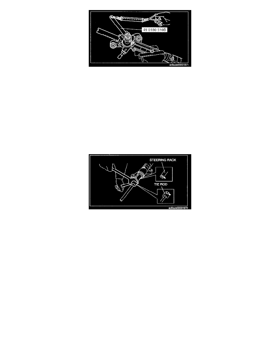
9. Measure the pinion torque using the SST and pull scale. (Measurement speed: 0.5 - 2.0 rpm)
Pinion shaft rotation torque
Center of rack ±90°: 1.0 - 1.6 Nm (1 - 16 kgf-cm, 8.9 - 14 in-lbf)
[Pull scale reading: 9 - 13 N (1.0 - 1.3 kgf, 2.1 - 2.9 lbf)]
Except center of rack ±90°: Less than 1.68 Nm (17.1 kgf-cm, 14.8 in-lbf)
[Pull scale reading: Less than 13.8 N (1.4 kgf, 3.1 lbf)]
10. If not within the specification, repeat Step 4 to 9.
Lock Washer, Tie Rod Assembly Note
1. Temporary assemble the lock washer and the tie rod to the steering rack.
2. Lock the steering rack end against rotation with a wrench and assemble the tie rod.
3. Clamp the lock washer.
Steering Gear and Linkage Removal/Installation
STEERING GEAR AND LINKAGE REMOVAL/INSTALLATION
Caution:
^
Performing the following procedures without first removing the ABS wheel-speed sensor may possibly cause an open circuit in the
harness if it is pulled by mistake. Before performing the following procedures, remove the ABS wheel-speed sensor (axle side) and fix it to
an appropriate place where the sensor will not be pulled by mistake while servicing the vehicle.
1. Drain the power steering fluid.
2. Remove the front under cover A and front under cover B.
3. Remove the middle pipe.
4. Remove the transverse member.
5. Remove the front crossmember, steering gear and linkage component.
6. Remove in the order indicated in the table.
7. Install in the reverse order of removal.
8. After installation, adjust the total toe-in.