
Mazdaspeed6 L4-2.3L Turbo (2006)
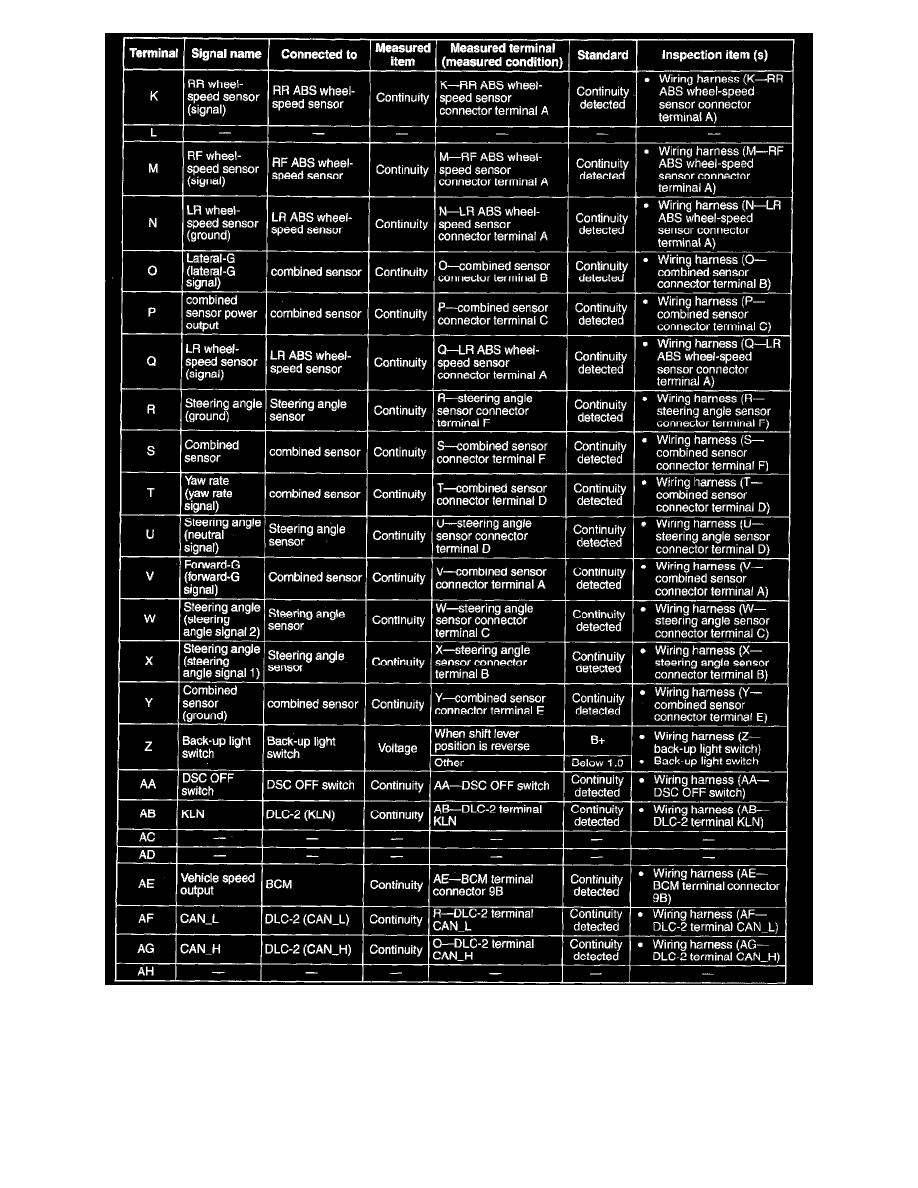
Terminal Voltage Table (Reference) (Part 2)
1. Disconnect the DSC HU/CM connector.
2. Connect the negative battery cable
3. Attach the taster lead to the DSC HU/CM wiring harness-side connector, then inspect the voltage, continuity, or resistance according to the
standard (reference) on the table.
DSC HU/CM Configuration