
Mazdaspeed6 L4-2.3L Turbo (2006)
1. Remove the TCM.
2. Connect WDS or equivalent to DLC connector.
3. Connect oscilloscope test leads to the following TCM connector terminals.
^
(+)lead: TCM terminal 2P
^
(-)lead: TCM terminal 1P
4. Start the engine.
5. Monitor VSS PID.
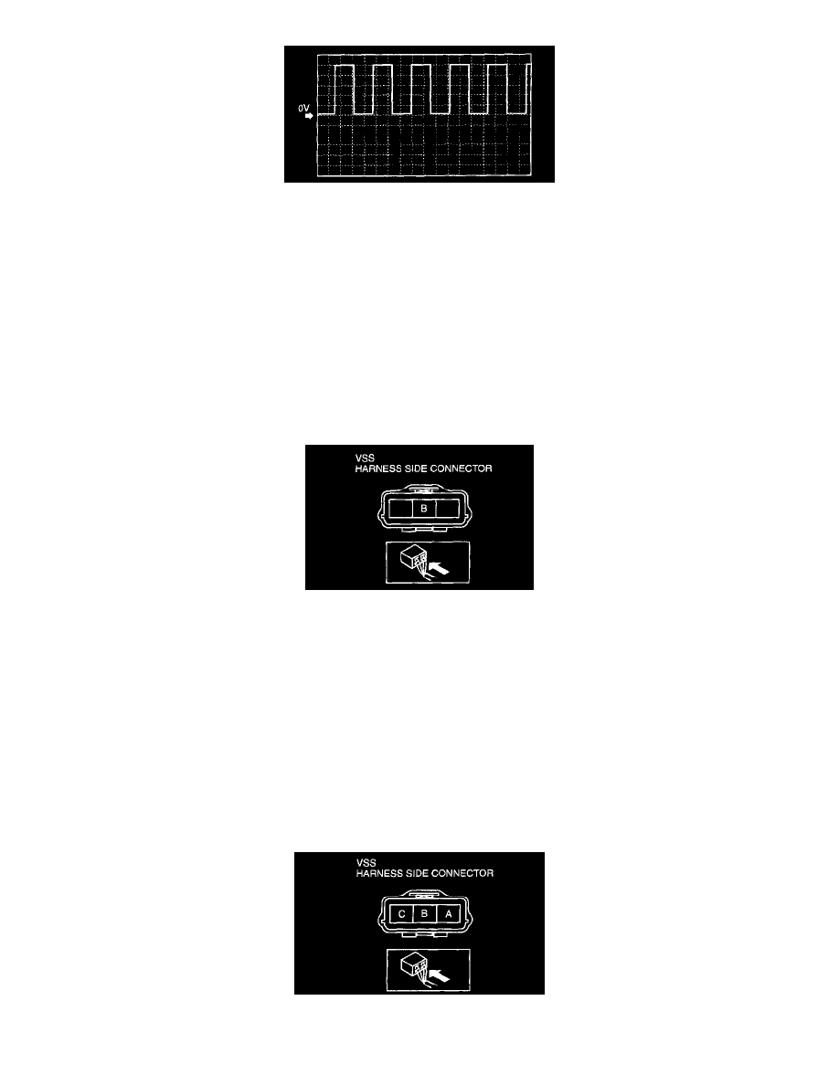
6. Inspect wave profile.
^
TCM terminal: 2P (+) - 1 P (-)
^
Oscilloscope setting: 1 V/DIV (Y), 2.5 ms/DIV (X), DC range
^
Vehicle condition: drive the vehicle with 32 km/h (20 mph)
-
If wave profile or voltage are out of specifications, carry out the "Open Circuit Inspection" or "Short Circuit Inspection"
Power Supply Voltage Inspection
1. Disconnect the VSS connector.
2. Turn the ignition switch to ON.
3. Measure voltage at VSS connector terminal B (wiring harness side).
Vehicle speed sensor (VSS) voltage 4.5 - 5.5 Volts
^
If voltage is okay, go to Open Circuit Inspection and Short Circuit Inspection.
^
If voltage is wrong, repair wiring harness between VSS and TCM.
Open Circuit Inspection
1. Inspect the following circuit for open.
^
Power circuit (VSS connector terminal A to main relay terminal D)
^
Ground circuit (VSS connector terminal C to GND)
^
If an open circuit or short circuit is found, repair the malfunctioning wiring harness.
^
If there are no open or short circuits, perform the sensor rotor inspection.
Short Circuit Inspection
1. Inspect the following circuit for short.
^
Power circuit (VSS connector terminal A to main relay terminal D)